|
July 1958 Radio-Electronics
 [Table of Contents] [Table of Contents]
Wax nostalgic about and learn from the history of early electronics.
See articles from Radio-Electronics,
published 1930-1988. All copyrights hereby acknowledged.
|
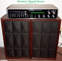
This proves you can find just about anything on eBay. Here is
my restored Reader's Digest Model 800-XR AM/FM stereo system 8-track tape.
My first major high fidelity (Hi-Fi) stereo system purchase came during my senior
year at
Southern Senior High School (1976 - ugh, so long ago!) when I had saved enough
money to buy a combination AM/FM receiver, 8-track tape deck, turn table, and two
speakers with separate woofers, midranges, and tweeters. At the time I thought the
setup might impress friends and relatives... until I learned quite quickly that
"serious" stereo sound connoisseurs decidedly did NOT have equipment with
"Reader's Digest" logos on it. Oh well, the price seemed like a really good bargain
to me give the promised tonal superiority. Compared to the clock radio I used previously
for my music listening sessions, the Reader's Digest stereo system produced music
hall quality sound. Ah, the deep bass notes were grand. Spending most of my earned
money on model airplanes, rockets, and my '69 Camaro left little disposable income
for LPs (referred to as "discs" in this article), so the turntable did not get much use. I did, however, read up on how to
balance the tone arm for just the perfect amount of pressure to assure top notch
music. What I was not aware of was that not all styluses used the same amount of
pressure, so I probably did more harm than good with my efforts. I did convince
myself, of course, that the music definitely sounded better after the painstaking
adjustments. This article brought that experience back into my mind.
How the Stereo Disc Works
The facts on the 45/45 system
By Norman H. Crowhurst
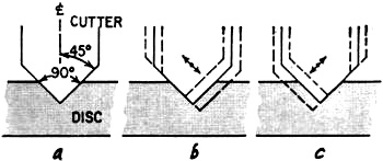
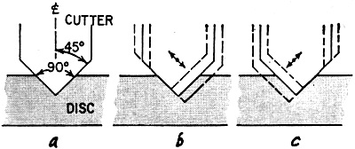
Fig. 1 - The basis behind the wrong idea that each channel
is cut into one wall of the groove in the 45/45 system: a - no modulation; b - modulation
in channel 1 appears to cut only the right wall; c - modulation in channel 2 appears
to cut only the left wall.

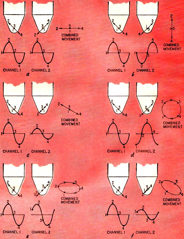
Fig. 2 - A more careful analysis of how the cutter, groove
and playback stylus move for different intensity and phase relations between channels
at anyone frequency: a - in phase; b - out of phase; c - intensity difference; d
- 90° phase difference; e - 30° phase difference; f - intensity and phase
(30°) difference.
A recent conversation about the stereo discs ran something like this: "How on
earth can a pickup stylus vibrate two ways at the same time and give different in-puts
for two preamplifiers?"
"That's easy," the answer came.
"Every groove has two walls and one recording is cut into each wall of the groove."
The puzzled expression on the questioner's face showed that this did not satisfy
him - and for good reason. It is impossible for the stylus to follow different contours
on both walls of the groove at the same time. This may have been a simple explanation
but it was certainly not the correct one.
In literature issued by Westrex the difference between cutting the two channels
appears somewhat as in Fig. 1. It shows a record cutter that has an angle between
the cutting faces of precisely 90°. The two drive mechanisms, arranged at 45°
to the vertical so the total angle between is 90°, drive this cutter in directions
parallel to its faces.
Consequently the diagram may make it seem that the vibrations due to one drive
are recorded in one wall of the groove while vibrations due to the other drive are
recorded in the other wall.
Stylus and cutter motion
In practice, there is invariably some program in both channels and both vibrations
occur at once. So it is more important to consider what happens to the point of
the cutter than to the contour produced by its two angular cutting edges. This is
because the pick-up stylus will (or should) ride in the bottom of the groove, cut
by the point of the cutter, and it is the movement of this point in the groove that
determines the program content of the two channels. To clarify this, let us consider
what happens with different program combinations.
If both channels carry the same program at the same intensity and in phase, the
movement of the cutter and the pickup stylus will be in the form of a lateral vibration
(Fig. 2-a). ("In phase" as explained further down, refers to the system phase,
not that of the cutter drive mechanisms.)
But if the inputs are precisely out of phase, the corresponding output from the
loudspeakers on playback should also be out of phase, with one loudspeaker pushing
when the other pulls. Then the motion of the cutter, groove and pickup stylus will
be up and down in a vertical direction (as shown in Fig. 2-b).
If both channels have the same frequency in phase, but the intensity of one channel
is stronger than the other, the motion will be predominantly lateral, with a slight
angle but less than 45° (as shown in Fig. 2-e).
If both channels carry the same fre-quency, but the phase relationship is neither
in nor out of phase, other move-ments can occur. At a phase relation-ship of precisely
90", the motion of the cutter and the stylus, will be in a circle (Fig. 2-d).
Other phase relations with equal intensity will produce an elliptical movement,
as shown in Fig, 2-e.
Finally, if there is a difference in both intensity and phase that does not correspond
with either an in-phase or out-of-phase condition, the motion of the cutter and
ultimately that of the stylus will be in a modified ellipse as shown in Fig. 2-f.

The ESL stereo pickup separates the movement right at the stylus.
This is the prototype model.

The Electro-Voice pickup uses two crystal elements. The Electro-Voice
cartridge, is shown in the insert on the cover with the lower part of the housing
(shown as white in this photo) removed and the copper clip normally attached to
it floating in air. The two ceramic elements are clearly seen at the base of the
red coupling element, running between it and the grayish mounting block at their
opposite ends.
The motions depicted by Fig. 2, of course, represent only what can happen
at one frequency at a time. As practical program material contains a variety of
frequencies, at various intensities and phase relationships, the cutter, and hence
ultimately the stylus, perform an endless variety of patterns, weaving in and out
and up and down.
This explains the nature of the groove and what it represents. Now we come to
the question of how this information is extracted from the groove by the pickup.
But before we proceed, let's clear up the question of phase, because different writings
and discussions on the subject use different terms of reference and apparent contradictions
arise.
Some refer the phase relationship, between the motion in different directions,
to the cutter or pickup mechanism while others refer it to the overall action of
the system. The definitions we have used so far, both in the previous article ("Single-Groove
Stereo Discs," Radio Electronics, January, 1958) and in this one, are related to
system phase. This is based on the desirability of the lateral direction of cutter
and stylus motion corresponding with the in-phase combination of program in the
two channels.
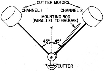
But, related to the simple cutter design shown in Fig. 3, an in-phase movement
of the two cutter mechanisms will drive the cutter vertically because the outward
thrust of both elements results in a downward movement while the inward pull results
in an upward movement.
To reverse the phase relationship to come out with the in-phase input to the
two microphones producing a lateral cut, all that is necessary is to reverse the
connections to one of the cutter coils. Similarly, if we take careful account of
the phasing at the pickup, we can reverse one of the connections between the pickup
and the amplifier or at the speaker, so lateral motion of the stylus results in
in-phase motion of the loudspeaker diaphragms.
So, if we talk about cutter or pickup phasing, in-phase action produces a vertical
cut and out-of-phase a lateral one. But referred to the system - the microphone
input or loudspeaker output, it is just the other way around. To avoid confusion,
references to phase in this article are related to the system rather than to the
cutter or pickup mechanism.
Now to the pickup
Basically a pickup for stereophonic discs can use the same kinds of transducer
elements, for converting the mechanical motion of the stylus into electrical output,
as nonstereo pickups. The more common forms are magnetic, moving coil, crystal and
ceramic. The way these elements operate follows precisely the same principle as
their single-channel forebears. Now we come to the real question, how do we separate
the two forms of vibration?
There are two extremes in the way this can be done. One method separates the
two movements at the stylus point and couples them by separate mechanisms to individual
transducer elements. This is the method used in reverse in the Westrex cutter head.
The stylus is carried on a fairly stiff rod, in line with the direction of the groove.
The two cutter motors are directly coupled to the stylus point at 45° in two
directions, as shown in Fig. 3.
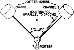
Fig. 3 - Basic action of Westrex cutter couples movement
in two directions right at the stylus.
The same method of coupling, applied to a moving-coil pickup, is exemplified
in the ESL stereophonic pickup, shown in the photos. It uses two d'Arsonval type
moving-coil mechanisms, similar to their well-known single-channel design, both
coupled to the same stylus. The stylus is the common point at which the drive separates
the two moving-coil transducers.
At the other extreme the stylus motion can be conveyed by a common arm to a pivot
or some kind of combination transducer where the two outputs are obtained electrically
by separation in the transducer action itself. An example that excellently illustrates
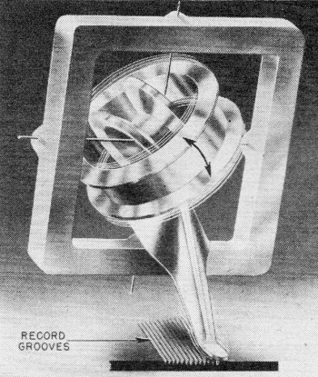
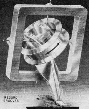
this method is the Fairchild stereophonic pickup.
The photos are a magnified view of the central element of the professional model
of this pickup. As shown, the bobbins are empty and the actual coils have not been
wound. The transparent plastic bobbins can clearly be seen at 45° to the square
frame. The thin wires passing through the centers of the side suspend the coil assembly
and provide a restoring force to center the coil in its neutral position.
The stylus arm, shown coming down at approximately a 45° angle, can move
in almost any direction and produce a corresponding combination movement in the
coil. The magnetic field that produces the electrical output when the coils move
is produced by pole pieces in front and behind the square. The magnetic poles are
not shown in the photo because they would obscure the mechanism.
Obviously, if the stylus moves at a 45° angle one way, one coil will be rotating
about its own axis and otherwise not moving and will produce no output while the
other coil will be rotating like a d'Arsonval coil between the two pole pieces and
produce an electrical output (Fig. 4-a ). Motion in the opposite 45° direction
will make the first coil produce an output, while the second one rotates about its
own axis and does not produce any output (Fig. 4-b).
This construction produces better than 20-db separation between the two motions,
over a frequency range extending from the low end up to the region about 10,000
cycles. Above this, separation is not so good, although the response of the pickup
is maintained.
These may be regarded as two extremes in method. Practical pickups may well bridge
the gap and produce results by methods that would be difficult to list under either
one of these extreme headings, perhaps coming close to achieving it by both of them.
Combination pickup

Fig. 4 (a, above, and b, below) - The Fairchild cartridge,
a moving-coil type, uses the same stylus arm to transmit the combined vibrations
to a double-coil assembly mounted in the same magnetic field.
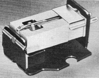
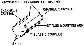
The new Electro-Voice design is one such method. This pickup is shown in the
photos and its basic operation illustrated by Fig. 5. Like the Westrex cutter,
the stylus is supported by a horizontal rod in line with the direction of the groove.
However, a much more flexible rod is used because a stereo pickup requires a high
compliance, or flexibility, while the cutter requires quite a reasonable stiffness.
Underneath the clip toward the right of the photograph is a removable mounting
for the stylus and rod, so it can readily be changed without replacing the pickup.
The stylus arm drives the crystals through a triangular piece of compliant or elastic
material. Motion at one 45° angle drives one crystal, while not moving the other
one and vice versa.
As a crystal is basically a stiffness or compliant device (the drive force is
used to bend it rather than move it) and these elements in this cartridge are rigidly
mounted at their other end, the compliant drive from the stylus arm to the crystal
represents a mechanical potentiometer, both elements of which are a compliance or
stiffness. This means that if the compliance of the coupling element is five times
that of the crystal then the motion at the tip of the crystal will only be one-fifth
of the stylus' motion in that particular direction.
As crystals produce a high output from a microgroove recording, this method still
delivers enough output for any high-fidelity preamplifier and it has the advantage,
over the more usual method of coupling through a mechanical lever system, that mechanical
lever resonances are completely avoided. The dominant mechanical impedance presented
to the stylus point is the compliance of the stylus arm itself and its elastic coupling
member.
If there is any mechanical resonance in the crystal element within the audio
range, it will modify the frequency response but will not produce the damaging effect
upon the record usually associated with crystals. Also the use of this "potentiometer"
arrangement restricts the magnitude of movement required in the crystal and lets
it operate in a range where it is essentially linear. Driving the crystal harder
(as the normal lever system does) would run it into nonlinear extremes.
With this pickup, separation of channels really takes place in the triangular
piece of compliant material. But as this is one piece of material and not two separate
links, it seems to "split the difference" between the extremes we started out with.
An advantage of this design is the relative purity of the separating method, achieving
a high order of discrimination against cross-modulation.
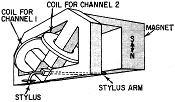
Other variations in the method of splitting the output can be seen by looking
at possible ways of doing it in a magnetic construction (see Fig. 6). Here,
the slug of magnetic material that produces the variation in magnetic reluctance
is attached directly to the stylus arm and varies the reluctance of both magnetic
circuits, one for each channel. Motion at one 45° angle will change the gaps
in that direction but not in the other direction, and there will be an output from
only one coil. Motion in the other 45° angle will produce an output from the
other coil. The complicated motion of the stylus following a stereophonic groove
produces an output from both coils in the desired stereophonic relationship.
What's the delay?
From this discussion it is evident that there are a variety of ways to make pickup
for stereo discs. Also it is evident that there are no serious problems in cutting
the discs. A feedback cutter, such as the Westrex, will do a good job of separating
the two channels and avoiding cross-talk, provided the two drives are mounted precisely
a 90° to each other. So what are we waiting for? Why have not standards been
laid down and records already in production, with pickups to play them?
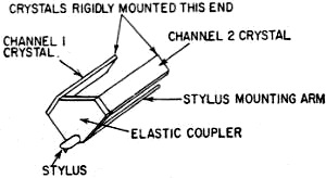
Fig. 5 - The Electro-Voice stereophonic pickup uses crystals
and transfers the vibrations through an elastic piece that separates them.

Fig. 6 - Another possibility is shown in this diagram of
a composite two-coil magnetic assembly.

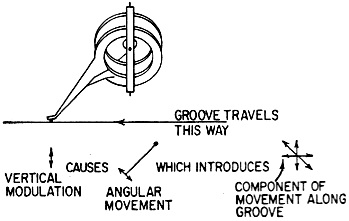
Fig. 7 - How an unduly steep stylus-arm angle might cause
the vertical component of stylus motion to frequency-modulate the recorded program.
Here we have a "which came first, the chicken or the egg?" type of problem. The
pickup manufacturers are looking for test records to determine how good their pickups
are, while the record manufacturers need some way to measure precisely what they
have cut on a recording. The pickup manufacturers are looking for a perfect or at
least adequate test disc or series of test discs, while the recording manufacturers
are looking for a perfect pickup or one adequately within range, to determine precisely
what they have on their recording.
Then there has been the decision about the appropriate groove contour - should
the angle be exactly 90° as suggested by Westrex, or would other angles, such
as the system proposed by CBS, also be suitable. Also the correct contour for both
cutter and stylus has not been selected. Will the contour now standard in the industry
for monogroove be used or some other contour? Then we need some way to test for
interchannel intermodulation, cross-modulation and other effects that were completely
unknown with mono-grooves, The official approval of the Westrex system (which is
interpreted to include the CBS technique) may hasten action in standardizing these
other points.
Perhaps we should point out here that there is a difference at the cutter end
between the drive being at precisely 90°, or two separate 45° angles, and
the angle of the cutter wedge being the same. If the stylus really runs along the
bottom of the groove, it is not important to have the angle of the groove a precise
45° or 90°. Any angle, so long as it is suitably standardized, will serve
the purpose. The important thing is that the stylus must be able to ride the bottom
of the groove correctly.
In the design and testing of pickups there are some problems to settle. For example,
the Fairchild professional pickup has a stylus-arm angle of about 45° sloping
forward (quite apart from the 45° angles of the coils themselves). If the stylus
only moves laterally, its motion will be similar to that of any lateral recording.
But if the stylus follows a vertical component, even though this may be a partial
component due to both the 45° elements, the up-and-down movement of the stylus
will also produce a component (approximately equal to it) back and forth along the
direction of the groove (see Fig. 7).
This will amount to a Doppler effect along the groove or will result in effective
frequency modulation by the vertical component, As the vertical component is not
confined to one of the program channels in 45/45, the combined vertical or out-of-phase
component of both channels will produce frequency modulation.
We could go on to theorize about this but the real question is, does it really
produce distortion? And if it does, is its effect audible as a deterioration of
program quality? This is one of many things that still have to be proved. However,
it is interesting to note that a new Fairchild pickup has a stylus arm that comes
much nearer to being horizontal.
Another thing, this discussion is based on the motion of the stylus remaining
simple at all times - we assume it pivots about the cross-bar junction in the center
of the coil. But if the vibrations runs into resonant conditions of the cross-wires
or stylus arm at any frequency instead of the stylus assembly vibrating as a whole,
the investigation becomes even more complex and it is possible that some form of
intermodulation or other distortion not yet considered may take place.
Each kind of pickup, and each design approach, will have its own problems. In
general, the simplest mechanism is most likely to avoid troubles. But the only real
way to determine the effect of these different possible forms of distortion is to
measure them - to get test discs with different frequencies recorded on the respective
channels, determine possible cross-modulation from one channel to the other, or
intermodulation of the audio on one particular channel by other tones on either
channel, etc., using discs yet to be made.
Finally, having discovered what degree of intermodulation or cross-modulation
exists with any particular pickup or record combination, we still have to determine
whether this is important in terms of the end result - listening to the stereophonic
program. It must be conceded that all of the pickups recently demonstrated have
produced quite listenable stereophonic presentation, even though a rigid theoretical
investigation might suggest that some terrible distortion occurs.
From the work done so far and the technological improvement achieved to date,
it is evident that stereo discs have a great future. There will be a little shakedown
period - getting the bugs out and determining what kinds of distortion really matter
or whether they are really present at all - and then it seems we shall have a golden
opportunity for getting stereophonic program at a cost no greater than regular LP's.
Posted January 21, 2022
(updated from original post on 8/3/2014)
|