|
May 1958 Radio-Electronics
 [Table
of Contents] [Table
of Contents]
Wax nostalgic about and learn from the history of early electronics.
See articles from Radio-Electronics,
published 1930-1988. All copyrights hereby acknowledged.
|
Breaking news from May 1958:
"Hardly a month passes nowadays without the announcement of some 'sensational' new
amplifying device. The great majority of these startling inventions, after their
brief flurry in the popular and technical press, disappear into oblivion. But we
believe that the Tecnetron,
just announced in France, has a brilliant and enduring future." Have you ever heard
of a Tecnetron? I didn't think so; neither had I before reading this article in
Radio-Electronics. I guess that pretty much negates the preceding prediction. The
holy grail of the Tecnetron, whose etymology in and of itself is worth reading about
(it's not what you would guess), is that its transconductance increases with frequency.
Construction is such that although it is fabricated from a shaped rod of germanium,
it has a current controlling component that acts like a cross between a triode vacuum
tube and a depletion mode field effect transistor. My guess is that the rapid improvement
of standard semiconductor junction field effect transistors rendered the Tecnetron
not just obsolete, but way too expensive to manufacture comparatively.
Great Britain Patent #GB941629A, "Tecnetron in semiconductor
devices," S. Teszner. Sept. 11, 1961
The Tecnetron: Competitor to the Transistor?
Neither spacistor nor transistor, this new semiconductor triode shows great promise
for the ultra-high frequencies
By E. Aisberg*
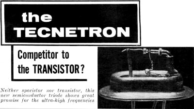
Close-up of a Tecnetron.
Hardly a month passes nowadays without the announcement of some "sensational"
new amplifying device. The great majority of these startling inventions, after their
brief flurry in the popular and technical press, disappear into oblivion. But we
believe that the Tecnetron, just announced in France, has a brilliant and enduring
future.
The most remarkable feature of this device i that it transconductance increases
with frequency, unlike more common semiconductor amplifiers whose performance falls
off as frequency increases and becomes very low as the cutoff frequency is approached.
Up to the present, frequencies in the order of 500 mc have been attained with the
Tecnetron. And, as further work and research make it possible to reduce the capacitances
of the contacts and other parts of the montage, there seems to be nothing to prevent
it from functioning at 1,000 mc or even higher.
It has been possible - with a Tecnetron working in class A at 500 mc - to obtain
a power output of 30 mw, with a dissipation of 125 mw. Since the characteristics
of individual Tecnetrons are very consistent, one can envision the paralleling of
several identical units to obtain watts - or even kilowatts - of power. This may
make it possible to use Technetrons in applications requiring heavy currents.
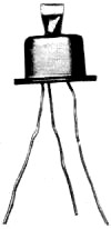
A Tecnetron unit in its case.
In addition, the Tecnetron - though using germanium - is less sensitive to high
temperatures than the transistor. It will operate at temperatures 20°C higher than
will transistors. This should extend its field of applications considerably.
Neither is it a fragile experimental device that works only under laboratory
conditions. Pilot production by regular industrial methods had begun on a small
scale at the time of its announcement. About 700 units per month are being produced,
and indications are that production could quickly be increased to the thousands.
What is the Tecnetron?
First, why is it the Tecnetron? The first syllable of the name begins as does
that of its inventor, S. Teszner. The initials CNET follow. These stand for the
Centre National d'Etude des Telecommunications (National Center for the Study of
Telecommunications), that great ensemble of research laboratories sponsored by France's
Ministry of Posts, Telegraphs and Telephones. And of course the final syllable is
the conventional one for such electronic devices.
Now, how is the Tecnetron constructed? It is a small rod of n-type germanium,
2 mm in length and 0.5 mm in diameter, provided with two contact electrodes at the
ends. These must be of such material that they act solely like electrical conductors
and not like transistor junctions.
The germanium rod is reduced in diameter at its center (Fig. 1) to form
a "bottleneck" of very small diameter (about 30 microns). Around this neck is placed
a cylinder of indium. This makes a metal-to-semiconductor barrier-layer contact
of excellent characteristics. The ratio of forward-to-back resistance is greater
than a million to one.
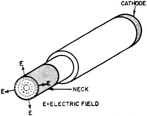
Fig. 1 - Tecnetron cut to show cross-section of neck. The
space charge E tends to drive the conducting area toward the center of the rod.
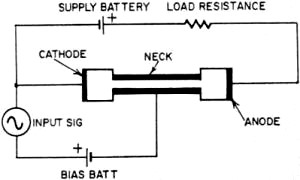
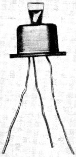
Fig. 2 - Schematic of Tecnetron hookup.

Fig. 3a - Distribution of charge carriers (electrons) with
neck unbiased; 3-b - reduction of current path caused by negative bias on neck.
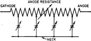
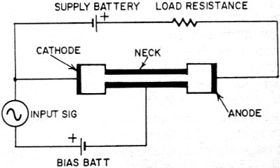
Fig. 4 - The Tecnetron can be considered as a variable resistance
and a distributed variable capacitance.

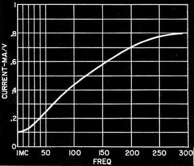
Fig. 5 - Variation of the Tecnetron transconductance as
a function of the signal frequency.
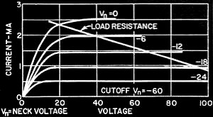
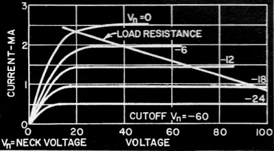
Fig. 6 - These Tecnetron static characteristic curves show
the variation of anode current as a function of anode voltage, for several neck
voltages.
A relatively high potential (50 volts or more) is applied to the electrodes at
the end of the rod. These may be called the cathode and anode. The cylinder of indium
might be called a grid, for it plays exactly that role. The inventor prefers to
call it the "bottleneck" or simply the "neck" to indicate its method of action better.
The neck is polarized negatively with respect to the cathode, and the circuit of
a stage of amplification (Fig. 2) is like that of a tube triode, with the load
resistance placed in the anode circuit in series with the supply voltage.
A field-effect transistor?
Is this device not essentially that which Shockley called a "field-effect transistor"
which he described in the Proceedings of the IRE (November, 1952; Vol. 40, pp 1365-76)
and with which he was not able to obtain appreciable gains above 2 mc? Like Shockley,
Teszner has turned to the field effect, discovered by Lilienfeld in 1928. Here the
resemblance ends. Whereas Shockley worked with plane surfaces (or a parallelepiped),
Teszner has utilized the cylindrical configuration, transforming a linear effect
to a quadratic one by applying a radial electric field.
What is the field effect? Our readers know of the Hall effect, due to which charge
carriers in semiconductors can be deflected from their paths under the action of
a magnetic field. The Lilienfeld effect is analogous to the Hall effect, but is
based on the action of the electric instead of the magnetic field. In semiconductors
such as germanium, charge carriers (electrons or "holes") can be deflected from
their paths by the action of such an electric field.
The Tecnetron action
The neck of the indium cylinder creates a concentrated electric field in the
interior of the rod, depending on the charge on the cylinder. With no charge whatever,
the current is propagated evenly through the whole area of the neck. As one applies
a negative voltage to the cylinder, the electrons are deflected toward the center,
occupying only a reduced section of the rod (Fig. 3). Thus the apparent resistance
of the rod increases as the active section - through which electrons pass - decreases.
This action is proportional to the square of the radius.
Note well that this is a variation in the total resistance, not in the specific
resistivity which remains constant.
The voltage applied to the indium cylinder causes the neck to act as if its diameter
were decreased. Thus the cathode-anode current is varied, causing the voltage across
the load resistor to reproduce faithfully the changes in the voltage applied to
the neck, but at a greater amplitude.
The best analogy of the Tecnetron is without doubt a flexible rubber hose through
which flows a current of water. If the hose is compressed more or less by the hand,
the flow decreases in the same ratio. If the hose is compressed circularly - from
all sides toward the center, as by an encircling thumb and forefinger - the diminution
of current will follow the square law. This centripetal constriction is an essential
characteristic of the Tecnetron.
Effects of capacitance
If we analyze these actions carefully, we note that the variation in resistance
is accompanied by a variation in capacitance between the part of the germanium occupied
by the electrons and the indium cylinder. As the cylinder becomes more negative,
it drives the electrons further from it and toward the center of the rod, thus reducing
the capacitance between the current-carrying portion of the rod and the cylinder.
As the voltage becomes less negative, the electrons flow through a larger section
of the germanium and the capacitance increases. The Tecnetron acts like the equivalent
circuit of Fig. 4.
These variations of capacitance, which are increased by the cylindrical configuration
of the device, have an effect on the current through the external circuitry similar
to that which the variations of resistance have on the flow of electrons through
the germanium. These two actions are synchronous and reinforce each other, thus
increasing the gain. There is of course a very slight detuning effect in resonant
circuits due to the instantaneous variations in capacitance produced by the signal.
These are very small, since the total input capacitance is a fraction of a micromicrofarad
and the detuning is proportional to the square root of the capacitance change. Practically,
according to the inventor, it manifests itself as a slight enlargement of the passband.
The capacitance effect, with its reduction of impedance as frequency increases,
is one of the reasons for the high transconductance at high frequencies (Fig. 5)
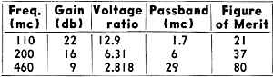
and the fact that the Tecnetron's figure of merit continues to increase with frequency.
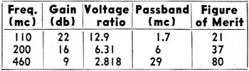
The figure of merit is the product of the gain by the width of the passband over
which the gain is maintained at ±3 db.
Tecnetron as amplifier
We have seen that the neck which acts as a control electrode is polarized negatively
with respect to the cathode. Thus no appreciable direct current can flow in the
cathode-neck circuit, because of the extension of the barrier layer into the n-type
germanium.1
Under these conditions, the input resistance is several megohms. The input capacitance
is in the order of 2 μμf.
The output impedance is generally higher than 1 megohm, and the load resistance
thus may be chosen as high as it is practically permissible to set it; usually between
2,500 and 250,000 ohms.
If we plot the characteristics of the Tecnetron by measuring the anode current
as a function of the anode-cathode voltage at various values of neck voltage, we
obtain a family of curves which resemble strikingly those of a pentode tube (Fig. 6).
Which is to say, that we have here an excellent voltage amplifier. The chart shows
experimental results obtained at various frequencies.
Manufacturing the Tecnetron
It was necessary to develop special technical methods to manufacture the Tecnetron.
This was one of the major achievements of M. Teszner and the CNET researchers who
aided him. For part of the work, the classic procedures of transistor production
could be followed. Then a whole series of new mechanical operations intervened:
cutting the refined crystals into plates, then into little rods. This last operation
was performed with ultrasonic cutting apparatus. The constriction for the neck was
made by a procedure of electrolytic etching perfected especially for the purpose.
The indium was also deposited by electrolysis, with the rod in continuous rotation
during the process. More conventional techniques could be used in applying the terminal
(cathode and anode) contacts.
Up to the present, procedures already developed permit manufacture on a large
scale. Research is continuing, however, and the next step is the creation of a power
Tecnetron and another model especially for ultra-high frequencies. Special arrangements
which will permit continuing still further up the frequency spectrum are also under
study. And, as always, as the area of actual accomplishment is increased, the greater
become the prospects of future progress.
* Publisher, Toute la Radio, Television, Radio Coustructeur et Deuarmeur, Eleetronique
Industrielle (Paris).
1 M. Teszner, Revue Génèrale d' Electricité, June,
1954.
Posted April 23, 2020
|