|
February 1968 Radio-Electronics
 [Table of Contents] [Table of Contents]
Wax nostalgic about and learn from the history of early electronics.
See articles from Radio-Electronics,
published 1930-1988. All copyrights hereby acknowledged.
|
Electronics industry
trade magazines used to like to print what I refer to as
technodramas™, which
were stories that had a plot centered around a technical issue. Sometimes it was
circuit troubleshooting, design, customer interaction, component reliability,
availability of technical information, supply chain problems, hired help
troubles, finances, or any other thing involved in the operation of an
electronics service business.
Mac's Radio Service Shop is probably the most well-known example, but there
was also
Carl and Jerry and similar regular series. This "The Technician Who Knew Too Much"
story from a 1968 issue of Radio-Electronics magazine is an example of
a random technodrama™ that was not part of a series. The moral of this story
involves not being too proud to concede to the possibility that someone you
regard as being lesser in experience than yourself might be capable of solving a
problem which evaded your first attempts. Enjoy.
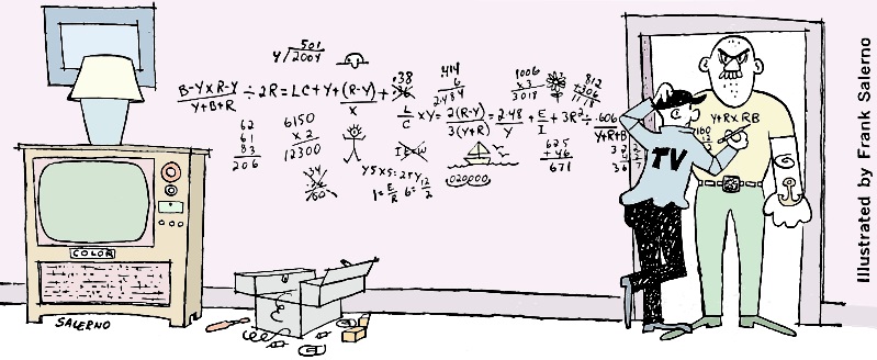
... or, don't sell the newcomer short
 By Wayne Lemons By Wayne Lemons
"It could be the picture tube," Jack said, "but I don't think so. It does have
the characteristic blink that a black-and-white tube gets when the cathode opens
intermittently, but since the color stays and since a color tube has three cathodes
I'm pretty sure they're not open and certainly not all of them."
Jack Cline - a tall, almost skinny, red-headed TV technician - was talking to
a customer. Jack is known as a good technician.
He belongs to a local civic club, takes part in the PTA, goes to church on Sunday
and yells good-naturedly at the referees at ball games. But Jack has never forgotten
that his chosen trade is electronic servicing and that he has to keep learning all
the time.
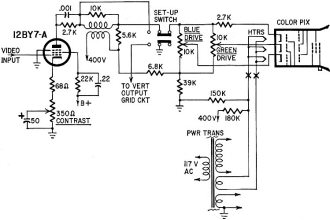
Fig. 1 - Jack scoped the grid, then the plate, of the 12BY7-A.
Signal on the grid was clean and steady; on the plate, it blinked. Could this be
a bad CRT?
And today, Jack would soon be wondering if he shouldn't go back to school to
learn more about throwing stones in glass houses.
An old friend (or at least that's what he'd always thought) had taken his color
set to the new technician in town. This guy had been a shop apprentice in the next
county and had just opened a place around the corner from Jack's. And Jack, with
more work than he could do, was happy for the competition.
Bad Picture Tube
The new man had diagnosed the trouble as a bad picture tube. Now Jack's "friend"
wanted an expert diagnosis ... "after all a picture tube costs a lot of money!"
Jack had stifled a natural inclination to sarcasm as to why he hadn't been consulted
first and continued, half to himself, "The video, all of it, is dropping out and
the only thing left is the color."
Jack turned down the color control to make a b-w picture; the picture blinked
off and on but there was no change in color or brightness. Or, if there was, it
was so slight as to go unnoticed.
"Can't you check the tube on your picture-tube checker?" his customer asked.
"The other guy didn't have one."
"I could," Jack agreed, "and I will, but don't expect too much. When it's an
intermittent condition you can't always depend on a test to find it. Mainly because
a picture-tube checker just doesn't put the tube under exactly the same stresses
that it gets in the circuit."
Jack got out the tester, set it up and made the checks on each gun. The tube
checked okay. Tapping the tube produced not even a flicker on the short-indicating
neons. The meter reading the emission of each gun held steady.
"Yes, I'd say the picture tube is good," Jack said. "Not just because of the
tester but because it seems impossible to me that anything in the tube could cause
all the video to drop out and yet the colored portions of the picture be okay. And
especially since the screen background color doesn't change and the brightness stays
normal. I'll get out the scope and see where we're losing the video."
Jack studied the circuit to decide where the best place to hook the scope would
be. The set was a Curtis Mathes with an RCA-type video-amplifier circuit; it was
dc-coupled all the way. This meant there just weren't too many things that could
cause a loss of video without also affecting the screen brightness.
One thing that might cause it, Jack decided, was leakage - perhaps between the
grid and cathode of a video amplifier. This would reduce the video level by reducing
grid bias. Even this, Jack realized, was far-fetched. But he tried the tubes. The
blinking continued intermittently.
The cathode is shorted to the filament, and we've got to separate
them.
Perhaps an open cathode-bypass capacitor? This would reduce the video without
affecting the plate current of the tube. Maybe an open screen bypass?
Jack decided to start by connecting the scope to the third video amplifier grid
(Fig. 1). The pattern was clean. When the blinking on the picture tube occurred,
the grid signal did not change. The trouble was isolated to the last video stage
or (heaven forbid!) the picture tube.
He moved the scope to the plate circuit of the third video amplifier. The trouble
cleared itself suddenly, but Jack knew the whimsy of circuits; the hiding out of
the culprit when the police get on the trail. He waited. The blinking returned and
at the same time the scope pattern blinked, becoming reduced in size and distorted.
What could cause the trouble? Perhaps it was a screen bypass. He bridged a new one
in. No change. Ditto with the cathode bypass.
He checked voltages on the plate, screen and cathode of the 12BY7 third video
amplifier. There was virtually no change when the blinking occurred.
Jiggle the Switch
Jack pored over the schematic. Could it be trouble in the set-up switch? He reached
over and jiggled it a couple of times. This seemed to have no effect on the blinking,
except that the trouble would clear for several seconds; but that happened no matter
how you disturbed the circuit. "And even if the setup switch was removing the video,"
Jack reasoned. "It shouldn't have much effect on the plate signal."
Something had to be causing a loss of video without affecting the circuit DC paths. A capacitor to ground somewhere? To probe this idea a little, Jack shunted
a 0.01-μF capacitor from the plate of the 3rd video tube to ground. This nearly
duplicated the symptom on the screen and the pattern on the scope. The video blinked
off and the scope pattern took a distorted dive downward.
But where was the capacitive leak-off of the signal? He followed the video circuit
from the plate to the picture tube. There was no wayward capacitor from some other
circuit causing the trouble. No leakage paths. It was another dead end.
"Oh no," Jack groaned, half aloud. "It probably is the picture tube."
The picture was blinking off and on regularly now, sometimes staying off for
several seconds. Jack eased the picture-tube socket off. The scope pattern on the
plate of the 12BY7 returned to normal size and shape. It stayed that way for 5 minutes.
The blinking was gone. Was it circuit whimsy or was it the picture tube?
He gently replaced the picture-tube socket. The picture stayed on 30 seconds
after the tube warmed up - then started to blink again.
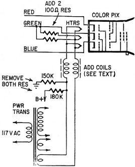
Fig. 2 - Jack's solution to the green heater-cathode short: isolation
coils.
"It's got to be the picture tube," Jack concluded. "But how? How is it possible
for a picture tube to lose all the video without losing the color or even changing
background color?"
He studied the circuit - all of it. Then it came to him. That had to be it. He
took a jumper and shorted two terminals going to the picture tube. It exactly duplicated
the trouble. The question, dear reader, is: What did Jack do and what was the trouble
inside the picture tube?
Jack used a jumper to short one of the cathodes to the heater circuit. This recreated
the trouble. There can be no brightness change because the heater is biased by a
bleeder on the B+ line so that it is near the same voltage as the cathodes. But
the video is skimmed off by the capacitance of the heater transformer windings to
ground.
"Is there anything you can do, old friend?" his customer asked.
"I'll see if I can burn out the short, but I've never had too much luck with
heater-cathode shorts," Jack said.
Jack looked at the circuit. Why not just ground the heater circuit? This would
place quite a lot of voltage between the cathodes and the heater. Maybe the short
would burn open.
Instead, something happened, but not what he had exactly hoped for. The short
became permanent. You could even measure it with an ohmmeter. It was the green cathode
shorted to its heater ... now solid and tight.
"Not much I can do except put in a new picture tube," Jack said, "but for a really
good friend who might have to tolerate just a little drop in video quality I can
install a circuit that will make this old tube work pretty well, perhaps."
"Go to it," his customer said.
Jack wound two coils of No. 20 enamel-coated wire in a single layer on a ferrite
core taken out of an old radio antenna circuit. Each coil was about 2 1/4 inches
long. He inserted them in series with the heater windings at point "X" (Fig. 2).
He removed the heater-biasing resistors and tied the green cathode though 100-ohm
resistors to each side of the heater circuit. (He couldn't tie the cathode direct
to the heater because the short inside the tube was not at the end of the heater
winding. But the short might not be permanent. Should it remove itself the 100-ohm
resistors would keep the heater winding biased.) The ferrite coils would pass the
heater current and at the same time keep the video from being bypassed to ground.
The new circuit worked even better than Jack had dared hope. Jack thought about
the new technician. He knew that the guy had instinctively but accidentally arrived
at the correct diagnosis. He wondered if sometimes you "knew" too much for your
own good. One thing was consoling though: Jack was pretty sure the new guy couldn't
have salvaged the old tube.
And Jack, still a little rankled because his friend had gone to the new guy first,
almost wished the jerry-built circuit hadn't worked. But then he smiled to himself
... of such things are reputations made. R-E
Posted April 26, 2023
|