|
September 1958 Radio-Electronics
 [Table
of Contents] [Table
of Contents]
Wax nostalgic about and learn from the history of early electronics.
See articles from Radio-Electronics,
published 1930-1988. All copyrights hereby acknowledged.
|
Here is a short tutorial
on how to design a resistive impedance matching circuit for feeding multiple transmission
lines of equal impedance. Both series and parallel feeds are presented. As the author
mentions, ideally you would like a lossless transformer for matching, but often
a resistive network is acceptable, especially if receive signal power is not an
issue and if your transmitter power is sufficient to overcome the resistive losses
(and doesn't torch the resistors). It is also possible to match transmission lines
of different impedances, but the equation would get messy. Although it would mean
even more resistive loss, the simplest way to match unequal impedance lines is to
first match to a value most of the lines exhibit, then build a separate resistive
transformer for the line(s) that are different to connect between the main match
network and the unequal line(s). That sounds confusing even as I write it, but it
is correct ;-)
Transmission Line Matching
Fig. 2 - Shunt connecting two-lead
lines. All lines have a common ground.
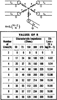
Fig. 1 - Series connecting coaxial
lines.
By Henry A. Kampf
Resistance match three or more lines to one antenna
Connecting three or more transmission lines poses the problem of proper impedance
matching to minimize standing waves in the system. Ideally, lines would be matched
with RF impedance-matching transformers which do not dissipate energy. Therefore
the RF power would be equally divided among all of the lines.
Lines can also be matched properly with ordinary 1/2-watt carbon resistors, if
the lines all have the same characteristic impedance and if the power lost in the
resistors does not reduce the signal below a usable level. This condition occurs
in strong-signal areas where several receivers are connected to a common antenna.
Any mismatch can cause standing waves which appear as ghosts on the TV screen. In
such areas reduction in signal strength is not important but the match of the RF lines is quite critical. Similar situations occur with test equipment and occasionally
in amateur applications.
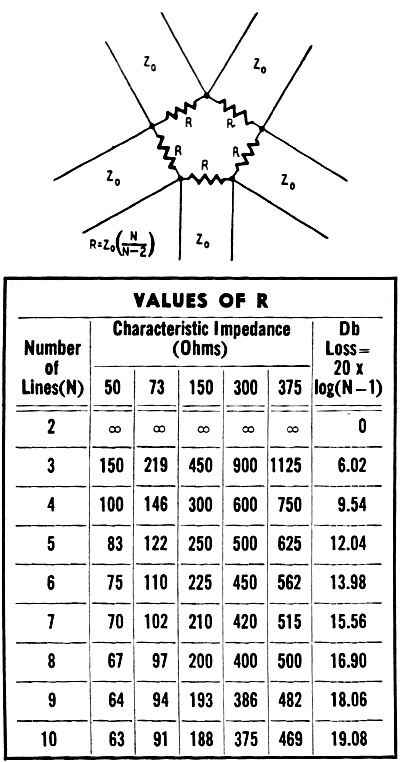
When matching with resistors, two connections are possible. The series resistor
connection is used for lines having a common ground, such as coaxial cables. The
shunt resistor connection can be used with balanced lines Figs. 1 and 2 show how
the matching networks are connected and give the formulas for calculating the necessary
resistor values. The symbols used in the equations are: Z0 - characteristic
impedance of the transmission lines used; N - total number of lines that are joined;
R - resistor value required in the diagrams.
When one of these lines is a signal source, the loss of the network for this
signal down to anyone of the other lines is calculated from the equation L = 20
log (N - 1), where L is the loss in db. This equation is the same :for either the
series or shunt connection. In the examples of Figs. 1 and 2 five lines are joined;
therefore, N is 5. If 300-ohm transmission lines are used, Z0 is 300.
Substituting these values into the equations we find that the required resistance
R is 180 ohms for the series connection and 500 ohms for the shunt connection. The
signal strength appearing on anyone of the lines will be 12.04 db down from the
signal applied to anyone of the other lines.
Posted September 6, 2021
(updated from original post on 9/8/2014)
|