|
June 1954 Radio-Electronics
 [Table of Contents] [Table of Contents]
Wax nostalgic about and learn from the history of early electronics.
See articles from Radio-Electronics,
published 1930-1988. All copyrights hereby acknowledged.
|
About the only kind of
transmission line homeowners use today is 75 Ω coaxial cable for
television and Internet connections. Up until the turn of this new century (two
decades old by now - ugh!), a fair percentage of TV owners still had an antenna
mounted on the roof or maybe rabbit ears sitting atop the set. Twin lead transmission
line was still a common sight as at least the "last mile" (last few inches,
actually) connection via an impedance converter to the pair of screws on the
back of a TV or FM radio. By then, most TVs also had an "F" coaxial connector
for direct attachment without a converter. Internet connections at the time
were telephone cords connected to the modem board inside your computer. It's
hard to believe that was just a relatively few years ago that we early World
Wide Web (WWW) users got to cross our fingers when dialing up a local phone
number for AOL, Earthlink, Compuserve, Prodigy, Mindspring, etc., and hoping
those handshaking squeals resulted in a successful connection rather than hearing
the number get dialed again for another try. Aside: When I made a household
move in 1996, it took me two months to get basic telephone service to the new
house because the WWW craze resulted in so many people having second lines added
just for online service that no lines were available for new service. That really
sucked.
Pointers on using these elements to improve performance

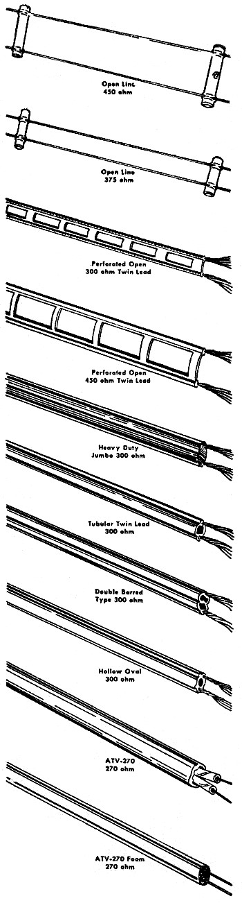
Several popular types of transmission lines used in u.h.f.
installations.
By Matthew Mandl and Edward Noll
The proper type of transmission line and its installation are important factors
in getting the most from a u.h.f. installation. Capacitance losses are greater
at u.h.f. Therefore the transmission line should be spaced at least six inches
or more from the mast or other metal objects. Even with a wide spacing it is
best not to run the line parallel to rain pipes or other metal conduit for any
great distance. The line should be as short as possible, and sharp bends should
be avoided.
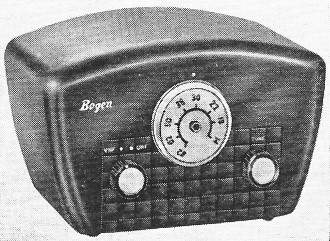
A standard U.H.F. television converter.
Line having the least loss should be used, though installation factors may
alter such a choice. The open-wire line, for instance, has much lower losses
than other types, but is most difficult to install, particularly where it enters
the home. The new Gonset u.h.f, open-wire line has an impedance of 375 ohms
with a 2-db loss at 500 mc. Imperial has a 250-275-ohm open-wire line which
matches 300-ohm loads and has a loss of about 0.8 db per 100 feet at 500 mc
when dry. As shown in the table on page 39 of the January issue, other lines
have a greater loss for this frequency. Since losses are calculated on the basis
of 100-foot lengths, the other lines can be used for ease of installation, provided
too great a length is not required.
Losses increase for the higher u.h.f. channels and too lengthy a run will
cut down the signal appreciably. Thus, if the antenna is raised by 100 feet
the additional length of the ribbon lead would introduce over 3 db loss around
channel 19 and almost 5 db for channel 83. A 5-db loss is greater than the gain
realized by stacking an antenna (3 db for each bay added to an existing antenna).
The tubular type line is preferable over the flat because of its lower loss,
but precautions must be taken to seal the ends of the line to keep out moisture.
Some technicians form a reverse loop in the tubular lead-in at the antenna to
keep out moisture, and also provide a drain hole by cutting a slot in the bottom
of the line where it enters the home. When the top is sealed, however, a loop
is avoided and a neater installation results.
The American Phenolic Corp. manufactures a polyethylene end seal plug which
provides a quick and positive closure for tubular lead-in. It seals the inside
of the tubular lead and also provides a protective cap and seal for the outside.
(Amphenol, 66-213 Twin-Lead and seal.)
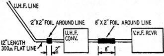
Fig. 1 - Using two sections of tin foil to minimize effects
of standing waves.
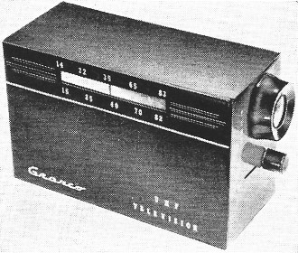
A compact type of U.H.F. converter.
The shielded wire lines are not recommended for u.h.f. installations. Their
excessive losses more than overcome their advantages-low noise (shielding),
plus unchanging impedance in wet weather.
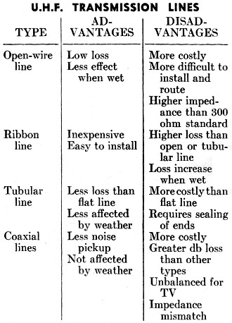
U.H.F Transmission Lines

The table lists the common advantages and disadvantages for
various types of u.h.f. transmission lines.
Uhf converters
Many u.h.f. converters have a gain of 1 and therefore do not increase the
signal strength during the conversion process. Thus it is essential that the
converter operate at peak efficiency. Otherwise signal strength will decline
during the conversion process. When there is reason to doubt the performance
of a converter, the tubes should be checked and the mixer crystal changed. It
is also a good idea to try several local-oscillator tubes as well as mixer crystals,
because certain combinations deliver greater signal output.
Some converters have provisions for both the v.h.f. and u.h.f. antennas.
The respective transmission lines are attached to the terminals and automatically
switched into position as the selector knob is turned to either u.h.f. or v.h.f.
In some converters such switches introduce capacitive losses. In weak-signal
areas such losses can be severe enough to degrade picture quality considerably.
A simple check consists of setting the converter for v.h.f. reception and tuning
in a weaker station. Remove the v.h.f. antenna transmission line from the converter
and attach it directly to the antenna terminals of the receiver. If there is
an increase in picture quality and contrast, the converter is introducing losses.
In such an instance it would be preferable to install a separate d.p.d.t. switch.
The switch within the converter can also be removed and the u.h.f. antenna coupled
directly to the input terminals, thus bypassing the switch losses.
Reception can be improved considerably by using tin foil on the transmission
line. This has always been helpful on the upper v.h.f. channels to minimize
the effects of standing waves and antenna mismatching. Results for u.h.f. are
also excellent. Best results are obtained if two sections of foil are used,
as shown in Fig. 1. Such foil is not as effective on the tubular or heavier
insulated transmission lines. For best results with such types, add 12 inches
of ordinary flat line between the u.h.f. antenna terminals and the u.h.f. transmission
line.
A 2-inch section of line works well prior to the converter, while a section
from 6 to 8 inches should be used on the line that runs between the converter
output and the antenna terminals of the receiver. A slight adjustment of each
section of foil for the weakest u.h.f. stations will make a considerable difference
in reception.
Posted March 3, 2021
|