|
January 1954 Radio-Electronics
 [Table of Contents] [Table of Contents]
Wax nostalgic about and learn from the history of early electronics.
See articles from Radio-Electronics,
published 1930-1988. All copyrights hereby acknowledged.
|
This statement by Bruce
Richards is an absolute truism, especially regarding ultimate system performance:
"Transmission line lead-in is a necessary evil. The service technician should not
regard it lightly. The best antenna and the best receiver in the country may not
give satisfactory reception unless serious attention is paid to the connection between
them." Gauging from some of the reader-submitted questions over the years to
QST magazine columnists, a lot of people do not fully understand and/or appreciate
the significant role the transmission line between the antenna and transmitter/receiver
plays. Much more concern is expressed over loss of power out during transmission,
but few seem to consider how the received signal is impacted due to resistive and/or
mismatch losses in the transmission line. The minimum discernable signal (MDS) is
directly affected, dB for dB, by line loss, so minimizing loss is extremely important
when you need to receive weak signals. Note in the Figure 1 graph how much
lower loss tubular type twin lead transmission line - which is not manufactured
anymore as far as I know - exhibits in wet conditions.
Transmission Line Lead-In for U.H.F.
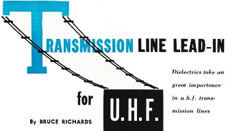
Dielectrics take on great importance in u.h.f. transmission lines.
By Bruce Richards
Transmission line lead-in is a necessary evil. The service technician should
not regard it lightly. The best antenna and the best receiver in the country may
not give satisfactory reception unless serious attention is paid to the connection
between them.
There are no certain tests by which the service technician can determine which
is the best type transmission line lead-in. Any transmission line attenuates the
signal. Theoretically, the best transmission line is the one that couples the antenna
to the receiver with the smallest attenuation loss. The problems involved are different
for u.h.f. than for v.h.f. At ultra-high frequencies the losses are greater. A typical
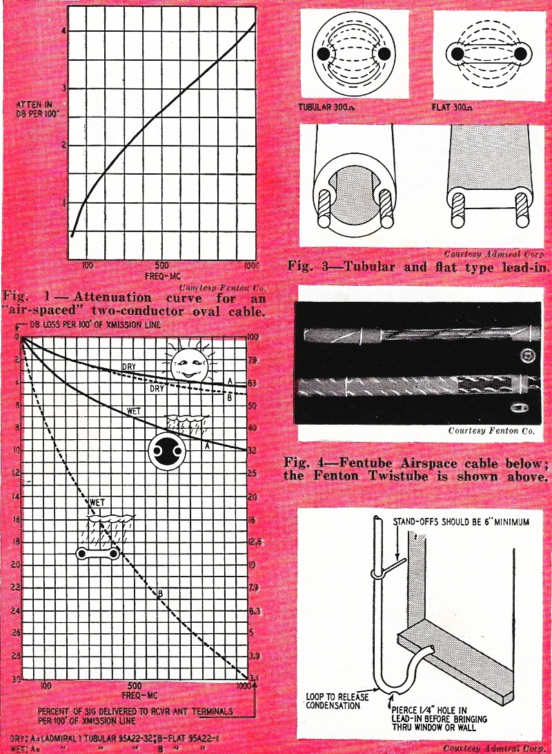
attenuation curve is shown in Fig. 1.
We are going to present some of the fundamental principles of transmission line
cable for u.h.f. lead-in and will make comparisons between cables now on the market.
The attenuation losses for several types of line will be indicated. The effect of
weather on the lines will be indicated where data are available. See Fig. 2.
Nothing will be said about the effects of mismatch. Obviously, the more closely
matched the antenna, line, and receiver, the less will be the attenuation and other
mismatch losses.
Let's confine ourselves to three basic types of u.h.f. lead-in line: open wire,
ribbon, and tubular twin-lead cable.
Open-wire line
The open-wire line has a lower attenuation figure than other types. This attenuation
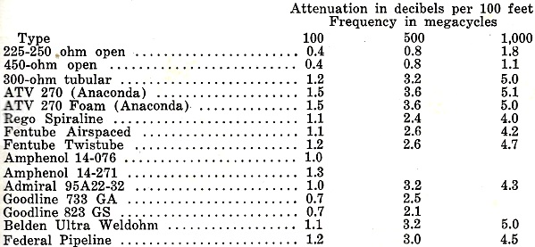
is approximately 1 db per 100 feet at the center of the u.h.f. spectrum. See Table
I.
Where it is necessary to run an exceptionally long. lead from antenna to receiver
this wire will hold to the low attenuation limit necessary for such an application.
Or, if it is possible to run a lead-in completely indoors so that it will be shielded
from weather, this is an ideal lead-in.
There are some disadvantages which make this wire a headache to the service technician.
It is difficult to mount, and it requires special care to avoid changing the spacing
of the wires between the insulators. Matching to a 300-ohm impedance is a serious
problem, because the characteristic impedance of open-wire line is 225-250, 375,
or 450 ohms.
A desirable characteristic of this type of line is that there is practically
no difference in its attenuation under wet or dry conditions. This is the only type
of line for which it can be said that if the picture is good under dry conditions,
the picture will be good under wet conditions.
Punched-ribbon line
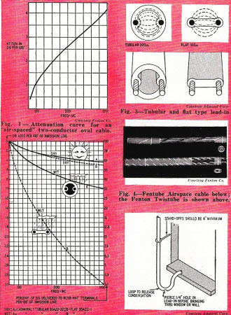
Fig. 1 - Attenuation curve for an "air-spaced" two-conductor
oval cable. Courtesy Admiral Corp.
Fig. 2 - Comparison of transmission lines under wet and dry conditions.
Courtesy Admiral Corp.
Fig. 3 - Tubular and flat type lead-in. Courtesy Fenton Co.
Fig. 4 Fentube Airspace cable below; the Fenton Twistube
is shown above. Courtesy Admiral Corp.
Fig. 5 - Diagram shows tubular transmission line lead-in at point
of entry.
Tests made under all types of weather conditions along seacoast sections have
shown that the average flat or round 300-ohm lead-in will give only a short period
of satisfactory service. The quality of the picture then deteriorates rapidly and
remains at a low level, as a result of the salt-spray deposits which encrust the
lead-in. Similar problems exist in areas where there is a hot, humid climate, where
much alternate rainfall and strong sunlight prevail, or where the lead-in is subject
to frost, snow, and ice.
One solution to this problem, which permits use of ribbon line for some locations,
is to punch out rectangles about an inch long and use short ribs to support the
wire at these inch intervals. This line has certain outstanding features. Eighty
percent of the loss-producing dielectric web is eliminated; the nominal 300-ohm
impedance is correct for a large number of receivers and antennas; it is lower in
cost than other lead-lines; and by insuring correct spacing of the flexible stranded
conductors, less than 1% of the operating wavelength is radiation loss.
Ordinarily, attenuation losses of unpunched twin-ribbon type lead are greater
than that of the punched-ribbon lead, except when water droplets accumulate in the
punched-out areas. The losses of punched lead are then very high; but this condition
disappears when the line dries out.
This punched type of line is good for an inside installation where it can be
kept clean and dry and would not be subject to the lossy effects of weathering.
Attenuation losses are moderate; it is flexible, easy to install; it fits into standard
insulators; and it does not present any impedance-matching problem.
Tubular cable
Each new advance in television brings along a number of accompanying advances
in associated products. The u.h.f. boom has encouraged the development of a large
variety of tubular-type twin lead-in cables. This is the type that is likely to
win general acceptance because it seems to provide the best over-all characteristics
for good u.h.f. reception under all conditions of installation, as well as with
aging and weathering. See Fig. 3. In tubular 300-ohm lead-in, the extremely important
field of energy is concentrated on the inside and is virtually unaffected by weather
conditions. In flat 300-ohm lead-in, the field of energy is largely outside, exposed
to all weather conditions and subject to signal loss.
The basic patents on putting two or more conductors inside a cable are over 50
years old. This means there is little room for invention in this field beyond minor
improvements. Hence manufacturers have been concerned with producing as good a wire
as possible with the lowest possible attenuation losses.
The published attenuation figures for a variety of these tubular twin cables
are in Table I. Some data were not available. For the most part these are laboratory
experimental data: what the data would be with respect to. actual reception of a
u.h.f. station is not known for the most part. This would be desirable information,
but it is not available.
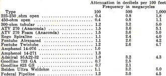
Table I - Transmission Line Attenuation
All the u.h.f. receiver manufacturers usually purchase a number of·competing
types of cable, and, set up some experimental procedures to determine the performance
of the lead-in under ideal conditions, under wet conditions, and to determine results
of aging. These data become a company report and unless the information is released
the service technician, who would profit much from such information, is not likely
to see it.
The data on the Rego Spiraline given in this table were obtained under actual
test conditions of a u.h.f. station operating in the 700-mc region. Incidentally
this was the best performing tubular cable out of a group tested under dynamic conditions
in the metropolitan New York City area. This is a novel design twin-lead wire, using
a solid conductor. Let's look at it more closely.
Air is the most desirable dielectric for the twin-conductor cable now commonly
used for v.h.f. and for the tubular type cable being used for u.h.f. An ideal cable
would be a pair of air-supported twin conductors properly spaced inside a tubular,
cable. However, this can exist in theory only.
It is common to support the cables and to maintain them in their proper spacing
by means of a thin film of dielectric, sufficiently thick to serve the purpose of
maintaining uniform spacing. See Fig. 3, "tubular 300 ohm." The dielectric, by surrounding
the cable throughout its entire length, contributes markedly to attenuation losses,
since the highest energy field is in the straight-line path between the two. conductors,
Rego Spiraline has adopted a design featuring a thin wall of dielectric material
supporting the twin conductors at points such that the ratio of bare conductor to
dielectric-covered conductors is sufficient to permit maintaining uniform wire spacing
throughout the cable length and at the same time permitting most of the twin conductors
to be free of dielectric covering. The points at which the dielectric holds the
twin conductor to the wall of the tubular cable do not have to be opposite each
other; they may be staggered along the cable at alternate spots. The bottom cable
in Fig. 4 illustrates the design used by Spiraline.
This cable has low dielectric losses and superior characteristics under wet conditions.
This wire must be handled carefully during installation. Rough handling or sharp
bends will change the spacing of the bare conductors and affect the impedance characteristics
and attenuation losses of the wire. For the service technician who is very careful
in his workmanship, this is an ideal tubular type lead. The manufacturers have not
been pushing this wire because they don't know whether the service technician will
give it the installation care it requires.
Characteristic impedance
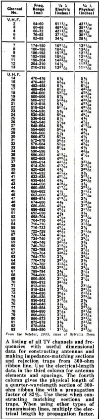
TV Channel Frequency Table
The characteristic impedance of a transmission line is important - more important
at u.h.f. than at v.h.f. because there is a relationship between the impedance of
a line and its attenuation losses. Both the size of the conductor and the spacing
of conductors affect the impedance of a transmission line. Standard tables of attenuation
losses show that losses are greater for lines with impedances less than 300 ohms,
For lines comparable in all other respects there would be greater losses fo a 280-ohm
line as compared to a 300-ohm line. Again, there is little the service technician
can do about this as the difference in spacing of conductors for 280 or 320 ohms
is negligible. Comparatively little wire is sold with a guaranteed impedance.
The spacing of the conductors varies from manufacturer to manufacturer for
a variety of reasons. Here are typical comments:
A. The spacing of the conductors was determined more by economic reasons than
any other. It was felt that it was best to keep the conductor spacing at the minimum
and so decrease the over-all size of the line, rather than get somewhat higher impedance
with a wider separation and therefore larger over-all dimensions.
B. The characteristic impedance of the flat and, tubular line is 300 ohms nominally
with a production tolerance of ± 20 ohms. For this reason it is possible
that the impedance could be 280 ohms and still be within tolerance.
Dielectric material
Most manufacturers advertise that their tubular cable is made with virgin polyethylene.
This may not always be true. Polyethylene is not available in the quantities necessary
to supply all demands by the wire and cable plants. Some of them are maintaining
production with a percentage or reused polyethylene. The Bakelite Company, manufacturer
of polyethylene, suggests, "The dielectric constant of reprocessed polyethylene,
we believe, is greater than that of new polyethylene due to the impurities which
are introduced either prior to or during the reprocessing operation. While we have
no data to substantiate our belief we do believe that reprocessed polyethylene attenuation
losses would increase more quickly with age due to impurities, as mentioned above,
which might be introduced either prior to or during the reprocessing operation."
Unfortunately there is little the service technician can do about such manufacturing
substitutions, as it is practically impossible to determine the difference between
virgin and reprocessed polyethylene. There is one clue which will help the service
technician get a good polyethylene wire. The smoothness of the finish on the tubular
twin-lead u.h.f. cable does influence the losses of the cable. If there is any roughness
on the outer surface of the polyethylene this rough portion would tend to catch
and be a collecting spot for dust, dirt, soot, and other foreign particles. Under
wet conditions this would tend to increase the losses for the cable involved.
Notes on tubular cable
Amphenol makes two types of tubular Twin-Lead cable: 14-076 and 14-271. The 14-076
is superior because of the following design and construction features:
1. The tubular design of the insulation reduces dirt and moisture concentration
in the field between the conductors. This means the impedance is constant for wet
or dry conditions.
2. 14-076 has seven strands of No. 26 wire as conductors rather than seven strands
of No. 28 wire as used in the 14-271 cable which has higher attenuation losses.
3. The design of the cable is such that there is a thin wall of dielectric covering
the wires and most of the field between the conductors is air. This is illustrated
in Figure 3.
The Fentube Airspaced tubular u.h.f. cable is illustrated in Fig. 4. This figure
also shows the Twistube. Both are made by the Fenton Company, New York City. For
most of the Fentube conductor length there is very little between the bare conductors
to interfere with the concentrated energy field. The No. 20 A WG conductors are
solid wires supported by means of the helical polyethylene wire-like cords.
The lines least affected by moisture and contamination are the new ATV-270 lines.
There are two types: the ATV-270 and the ATV-270 Foam. The Foam line is superior
at the high end of the u.h.f. band, because the attenuation losses are small. This
line uses two single solid conductors accurately spaced and firmly fixed in place
in foamed polyethylene. This line is so new there are no reports on it from field
tests as yet. These data are based upon the manufacturer's literature. The manufacturer,
Anaconda Wire and Cable Co., claims that attenuation characteristics for both types
of line are practically unaffected by moisture.
Installation
For new installations, 300-ohm flat line should be avoided for u.h.f., particularly
when long lengths must be used. There should be a minimum separation of 6 inches
from surrounding objects to prevent signal absorption losses. The standoffs should
keep the wire at least 6 inches from the building. Make a drainage loop in the line
just before it enters the house. Punch a hole at the bottom of the loop to remove
moisture condensation in the line (see Fig. 5). Avoid coils or kinks anywhere between
the antenna and the receiver. Cut the line to the proper size to reach the receiver
and do not leave any extra line which might be coiled up or kinked, causing impedance
changes.
Posted February 24, 2022
|