|
May 1958 Radio-Electronics
 [Table
of Contents] [Table
of Contents]
Wax nostalgic about and learn from the history of early electronics.
See articles from Radio-Electronics,
published 1930-1988. All copyrights hereby acknowledged.
|
You and I know them as "varactor
diodes," but originally the semiconductor junctions whose reverse bias determines
its capacitance was called the 'Varicap.' The new and wondrous semiconductor craze
was in full swing by 1958. Scientists, engineers, and hobbyists were burning the
midnight oil (to use a popular phrase of the day)
performing experiments and designing circuits to replace vacuum tubes and manual
controls with transistors and other electrically variable semiconductors. The Varicap
had the ability to tune receiver and transmitter oscillators and filters without
the need for high tube bias voltages and large mechanically variable multi-plate
capacitors. This article from Radio-Electronics says early Varicaps cost
$4.50 apiece ($39.95 in 2019 dollars per the
BLS Inflation Calculator), so they were not cheap by any account. However, their
cost was justified by reducing circuit complication (a mechanically variable capacitor
and possibly a vacuum tube), improving reliability (no moving parts to wear out,
vibration immunity, resistance to environmental factors), and the prestige of claiming
to be a modern 'electronically tuned' product.
Using the Varicap
By Rufus P. Turner
The capacitance of this startling little semiconductor, the size
of a 1/4-watt resistor, varies with he voltage applied to it.
The capacitance of a reverse-biased semiconductor junction varies with the reverse DC voltage-capacitance decreases as voltage is increased. This effect has been noted
in both diodes and power rectifiers. In selenium rectifier plates, for example,
the capacitance is comparatively large, often reaching 0.25 μ.f or more. Attempts
to use this voltage-sensitive capacitance have been thwarted by the comparatively
low reverse resistance of the junction - rather high currents are needed to effect
the capacitance changes, and the Q is too low for most practical applications. Also,
both the capacitance and reverse resistance are extremely temperature-sensitive
in ordinary diodes and rectifiers.
An important milestone was reached with development of the silicon junction diode.
This semiconductor device has capacitance in small but useful amounts readily varied
by the reverse bias. And the reverse resistance of the silicon p-n junction is so
high (often 10,000 megohms at -1 volt) that almost no current at all is required
to do the job. Essentially a high-Q component, the silicon junction is noted for
the stability of its capacitance over a wide temperature range. In research laboratories
during the past 2 years, the voltage-sensitive capacitance of the silicon p-n junction
has been used in experimental voltage-operated tuning, frequency modulators, automatic
frequency control, capacitor type amplifiers, tunable filters and numerous sensitive
remote-control devices. Workers who had been intrigued by the earlier dielectric
amplifier (using voltage-sensitive ceramic capacitors), only to be frustrated by
their severe temperature drift, have had their interest re-stimulated by the silicon
junction.
Now, a useful new semiconductor component, the Varicap (see Radio-Electronics,
January, 1958, page 45) has become commercially available. This simple, two-terminal,
p-n junction device, designed for use as a voltage-variable capacitor, opens new
vistas for the simplification of many electronic circuits. The number of applications
to old circuits and the possibilities for new circuits will be limited only by the
experimenter's imagination and ingenuity. No larger than most 1/4-watt resistors
and resembling a miniature crystal diode, the Varicap will do the work of a reactance
modulator tube or of a variable capacitor, both of which are many times its size.
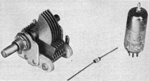
A miniature tuning capacitor and reactance tube dwarf Varicap
which may replace them.
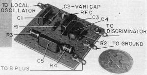
AFC circuit which you can add to FM receiver fits on 2 1/8 x
2 3/8-inch Phenolic board.
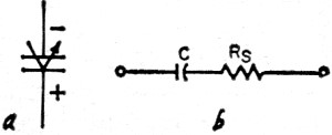
Fig. 1 - Schematic symbol and equivalent circuit of the
Varicap.
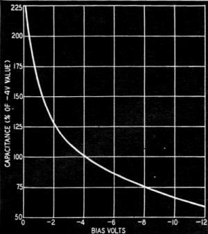
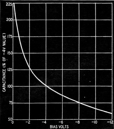
Fig. 2 - How Varicap capacitance varies with bias voltage.
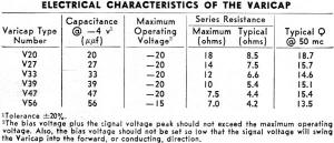
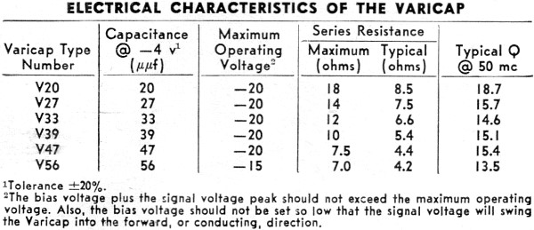
Electrical characteristics of the Varicap
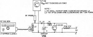
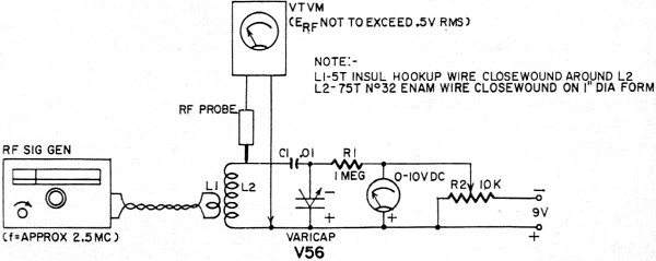
Fig. 3 - Test setup to demonstrate Varicap performance.
Varicap characteristics
Fig. 1 shows the schematic symbol and equivalent circuit of the Varicap.
The markings in Fig. 1-a indicate the DC bias voltage polarity. The positive
end of the unit is marked with a painted black band.
Fig. 1-b shows the equivalent circuit. Capacitance C varies approximately
as 1/√V, where V is the reverse bias voltage, and is practically constant
(for any given value of V) from -65°C to 150°C. Both capacitance and the
series resistance Rs) are substantially independent of the operating
frequency. The maximum frequency at which the equivalent circuit remains as shown
in Fig. 1-b is 500 mc.
Varicaps are available in six capacitances, as shown in the chart. These capacitances
are obtained with a DC bias of -4 volts. Capacitance tolerance is ± 20%. A Varicap
costs about $4.50.
Fig. 2 shows the capacitance variation with reverse DC bias voltage. This
curve applies to all types of Varicaps, regardless of their nominal capacitance,
and shows that each has 100% of the rated capacitance when the bias is -4 volts.
Only a few millimicroamperes of current flow when bias is applied to the Varicap.
Thus, virtually no power is required to vary the capacitance of this very-high-resistance
device.
Since the bias signal may be either steady or fluctuating, a variety of control
signals may be employed. The frequency range extends from DC to more than 500 mc.
In any application, the total voltage applied to the Varicap (that is, the DC bias voltage plus the signal-voltage peak when there is an alternating component)
must not exceed the unit's maximum operating voltage. Also, since the Varicap is
a diode operated in the reverse direction, the DC bias voltage should not be set
so low that the signal-voltage peak will swing operation into the forward, or conducting,
region.
The Varicap actually utilizes the capacitance of the p-n junction to do its job.
Why capacitance exists in the junction won't be rehashed here. Junction capacitance
in semiconductor devices is familiar to the reader; collector capacitance, for example,
is well known for its role in limiting the high-frequency response of transistors.1,2
In a conventional capacitor, a small leakage current flows through the dielectric
because it is not a perfect insulator. The higher the insulation resistance, the
lower this current. In a mica capacitor in good condition, dielectric resistance
may be 100,000 megohms or more, and the leakage current at low DC voltages so tiny
that it can be ignored completely. In a tubular paper capacitor, the dielectric
resistance may be as low as 1,000 megohms; therefore leakage current is much higher
than in a mica unit. The leakage current is highest of all in an electrolytic capacitor;
it may be an appreciable part of a milliampere. Because of leakage current, the
equivalent circuit of a capacitor shows a leakage resistance in parallel with the
capacitor plates.
The leakage resistance is so high in a mica capacitor that its shunting effect
is negligible. The dielectric between the plates approaching a perfect insulator,
there is (to all practical intents and purposes) no appreciable leakage path between
the plates, and the parallel resistance may be erased from the equivalent circuit.
Similarly, in the Varicap, the leakage resistance is extremely high (in the order
of tens of thousands of megohms) since the reverse-biased silicon p-n junction passes
only a few thousandths of a microampere. As in the mica capacitor, the parallel
resistance may be ignored and the junction considered a capacitance, since its
reactance is many orders of magnitude lower than the shunting resistance. The situation
is much the same as having a very good dielectric between the "plates" of the junction.
This capacitance varies, as explained earlier, with the impressed DC reverse voltage.
A conventional capacitor also has a series resistance component Rs.
At high frequencies, the magnitude of this resistance is due to the resistance of
plates, leads and various in-phase components of current. The Q of the capacitor
is affected by this series resistance. The Varicap also has an Rs component.
It is shown in Fig. 1-b and is specified for each type in the chart. The Q
of the Varicap (but not its capacitance) similarly depends upon this series component.
As mentioned earlier, however, this series resistance component is independent of
frequency up to 500 mc.
It is well to reflect that other semiconductor junctions, such as germanium diodes
and selenium rectifiers, pass much higher reverse (leakage) currents. These leakages
are not only higher than those of high-quality silicon junctions but increase markedly
with increased reverse voltage. In these units, because the leakage resistance is
often of the same order of magnitude or even lower than the capacitive reactance,
the useful change produced by changing the voltage on these devices is not exclusively
a capacitance change but rather a change in the impedance of the equivalent R-C
circuit. In this respect, the selenium rectifier somewhat resembles the electrolytic
capacitor with its high leakage. Quite to the contrary, the extremely high leakage
resistance of the silicon p-n junction and its useful capacitance identify it as
a high-quality capacitor.
Tuning Effect
One of the first applications that comes to mind is use of the Varicap as a voltage-variable
tuning capacitor in an L-C circuit. Fig. 3 shows the author's test setup to
demonstrate this effect and to check the tuning range for one set of operating conditions.
In this arrangement, C2 is a type V56 Varicap which serves as the tuning capacitor
of the L-C circuit, L2-C2. Capacitor C1 blocks direct current flow from the coil.
This capacitance is very large with respect to C2. Adjustable DC bias is supplied
by a battery through potentiometer R2. The bias level is indicated by the DC voltmeter.
Isolating resistor R1 blocks RF flow into the DC circuit but introduces no appreciable DC voltage drop because of the negligible direct current flowing through the Varicap.
An RF choke can be used in place of R1. The RF vtvm acts as a high-impedance resonance
indicator. The test signal is supplied by a conventional RF signal generator link-coupled
to the L-C circuit through coil L1. Coil L2 has been wound for resonance with C2
in the vicinity of 2 mc.
Near zero DC voltage, the Varicap has its highest capacitance (nominally greater
than 100 μμf) and the L-C circuit therefore is tuned to its lowest frequency.
At -9 volts, the capacitance is low (approximately 39 μμf) and the circuit
is tuned to its highest frequency. To keep within operating ratings of the Varicap,
the DC voltage should not be set to less than 1, nor the RF voltage, indicated by
the vtvm, to more than 0.5 volt rms.
To demonstrate the effectiveness of the Varicap as a voltage-variable tuning
capacitor: (1) Set the DC voltage to -1. (2) Tune the RF signal generator for resonance,
as indicated by peak deflection of the vtvm. Set the generator output control to
hold this deflection to 0.5-volt rms. (3) Record the generator frequency as f1.
(4) Set the DC voltage to -9, noting that the vtvm deflection falls indicating detuning
of the circuit. (5) Retune the generator to locate the new, higher resonant frequency
and record this as f2, The tuning range afforded by the 8-volt bias change is equal
to f2 - f1.
In the test setup shown in Fig.3, the circuit was tuned from 1400 kc at -1 volt
to 2250 kc at -9 volts, a tuning range of 850 kc. A wide frequency band may be covered
with the same capacitance change if L2's inductance is made smaller to increase
the operating frequency. In some applications of this principle, it will be desirable
to use the Varicap as a voltage-variable trimmer in parallel with an air tuning
capacitor.
Many applications of this principle suggest themselves. Examples are the voltage
tuning of RF test oscillators, local oscillators in radio and TV receivers (especially
in remote control operation), self-excited oscillators in transmitters and absorption
wave-meters.
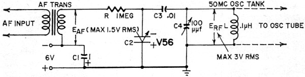
Frequency Modulator

Fig. 4 - Varicap frequency modulator circuit.
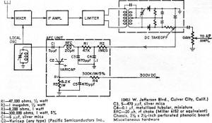
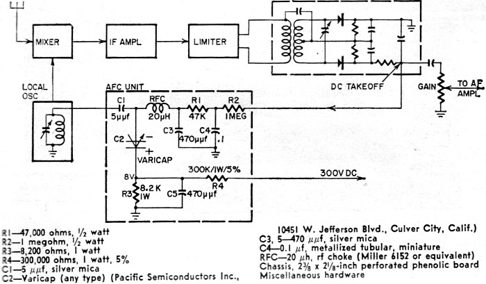
Fig. 5 - A Varicap AFC circuit for your FM receiver.
In the experimental circuit shown in Fig. 4, the Varicap (C2) is shunted
(through .01-μf blocking capacitor C3) across the tank circuit (L-C4) of a self-excited
50-mc oscillator. An audio-frequency voltage (af) is applied to the Varicap
in series with the 6-volt DC bias supplied by the battery. This AC fluctuates the
bias at the audio-frequency rate. The capacitance of the Varicap accordingly fluctuates
about its mean -6-volt value, frequency-modulating the oscillator. The center frequency
is determined by the setting of the 100-μμf air capacitor (C4) and the -6-volt
bias level.
Sweep width is proportional to the amplitude of Eaf and is adjusted
by varying this audio voltage. In Fig. 4, the RF oscillator is tuned to the
center frequency of 50 mc when C-4 is set to 50 μμf, the DC bias to -6 volts
and Eaf to zero. A 0- to 4-mc sweep is obtained when Eaf is
varied from 0 to 1.5 volts rms.
To prevent exceeding the Varicap voltage ratings in this kind of FM oscillator,
the sum of the dc, peak af and peak RF voltages must not exceed the maximum voltage
shown in the chart. Also, the DC bias must not be set so low that the sum of Eaf
peak and Erf peak will drive the Varicap into its forward, or conducting,
region, In Fig. 5, these conditions are met when Edc = -6 volts,
Eaf does not exceed 1.5 volts rms and Erf does not exceed
3 volts. While the latter is a relatively low RF tank voltage for tube type oscillators,
it is reasonable for high-frequency transistor oscillators with which the Varicap
frequency modulator is a natural companion.
Although the tank circuit shown in Fig, 4 has been designed for 50-mc operation,
it is not imperative that this frequency be used. The same FM scheme may be used
at other center frequencies by properly proportioning the L-C circuit. The lower
the center frequency, the lower the sweep width obtained with a given Varicap capacitance
swing, and vice versa, The transformer shown in Fig. 4 is not critical. Any
audio unit whose secondary will deliver a maximum of 1.5 volts rms audio from a
given af source is usable if it has a satisfactory audio response.
Automatic Frequency Control
The voltage-variable capacitance of the Varicap and its temperature stability
suit it for use as a simple, highly sensitive, afc device which performs better
than some reactance tube circuits. The small size of an afc unit, containing a Varicap,
four small capacitors, four resistors and an RF choke, lets you tuck it into a receiver
with a minimum of disturbance to the set's circuitry. This should be welcome news
to hi-fi enthusiasts whose FM receivers have no automatic frequency control.
Fig. 5 shows an afc circuit developed by Pacific Semiconductor engineers,
which I adapted for bias from the 300-volt DC supply of an FM receiver. The photos
show the complete unit ready for wiring into the receiver. Any type of Varicap may
be used. The receiver's local oscillator is simply realigned to compensate for the
shunting capacitance introduced by the biased Varicap C2 which functions as a frequency-controlled
trimmer across the local oscillator tank.
The Varicap is referred to a DC bias of -8 volts obtained from the receiver's
300-volt supply through the voltage divider R3, R4. The afc DC voltage is obtained
from one side of the discriminator. For other than 300-volt supplies, the values
of R3 and R4 will not be the same as mine but must be worked out for an output of
-8 volts from the particular supply voltage of the set that you are adding this
afc circuit to.
The completed afc unit is built on a perforated phenolic board 2 3/8 inches long
and 2 1/8 inches wide. The pigtails of the components are passed through the holes
in the board and interconnected underneath to complete the wiring. Printed circuitry
may be used. The four connections to the receiver circuit are made at solder lugs
mounted along the edge of the panel. The completed unit should be mounted as close
as possible to the local oscillator so that the lead from the tank to C1 will be
short.
((Certain silicon diodes can also be used as variable capacitors in such applications
as this. In the February-March, 1958, issue of Rectifier News, published by the
International Rectifier Corp., El Segundo, Calif., a circuit is shown for using
their 3DS1 silicon diode as an afc control device for an FM tuner. -Editor)
Other Applications
Other suggested uses for the Varicap include all-electronic dc-to-dc and dc-to-ac
choppers, amplitude modulators, alignment sweep generators, capacitor type amplifiers
(both AC and dc) , AC type flip-flops, automatic amplitude control in f oscillators,
FM telemetering and elimination of the fine-tuning control in TV receivers.
In some applications, Varicaps, like capacitors, may be operated in parallel
for increased capacitance and in series back to back for increased voltage-handling
capability.
1 William Shockley, Electrons and Holes in Semiconductors, D. Van Nostrand Co.,
1950, page 100.
2 D. C. Brown and F. Henderson. "The PN Junction on a Variable Reactance Device
for FM Production," Electronic Engineering, (London) November,
1957, page 556.
Posted August 15, 2019
(updated from original post on 6/11/2014)
|