|
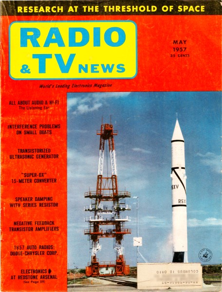
May 1957 Radio & TV News
 [Table
of Contents] [Table
of Contents]
Wax nostalgic about and learn from the history of early
electronics. See articles from
Radio & Television News, published 1919-1959. All copyrights hereby
acknowledged.
|
It took me a couple passes of the
explanation to comprehend the advantage of a Thomson-Varley (aka Kelvin-Varley,
since Thomson and
Lord Kelvin
are one and the same person) switchable voltage divider compared to a standard type.
At first I thought the author,
Edwin Bohr, was
implying that the source and load impedances would not have as great of an effect
on the accuracy of the divider (and to some extent it is less sensitive), but the
main advantage is that the configuration permits simple cascading stages of decade
dividers to achieve essentially any degree of resolution. Both a standard series-wired
type voltage divider and the Thomson-Varley need ten resistors and eleven switch
positions to provide 10 equal steps (plus bypass). However, using the same approach
for 100 equal steps in the standard divider scheme would require 100 resistors,
1000 steps would require 1000 resistors, etc. The Thomson-Varley divider cascades
decades of dividers so that 100 equal divisions requires only 20 resistors, 1000
divisions requires 30 resistors, etc. Such a 'breakthrough' idea was particularly
significant in the days when large radial lead components and multi-layered wafer
switches that were point-to-point hand-wired were all that were available, as compared
to printed circuit boards that are automatically assembled with pick-and-place robots
today. Obtaining large quantities of precision resistors is a lot easier nowadays
as well. Metrology laboratories still use Thomson-Varley type voltage dividers for
equipment calibration.
Note: Edwin Bohr does not appear to be a direct relation to physicist
Niels Bohr, although there
certainly must be some familial tie.
An Accurate Voltage Divider
By Edwin Bohr
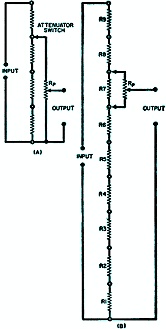
Fig. 1. - Attenuators usually found in test equipment (A)
are not accurate. In another type (B), the pot may load the divider resistors, upsetting
accuracy.

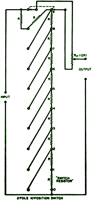
Fig. 2. - This precision divider uses a potentiometer in
the second decade.

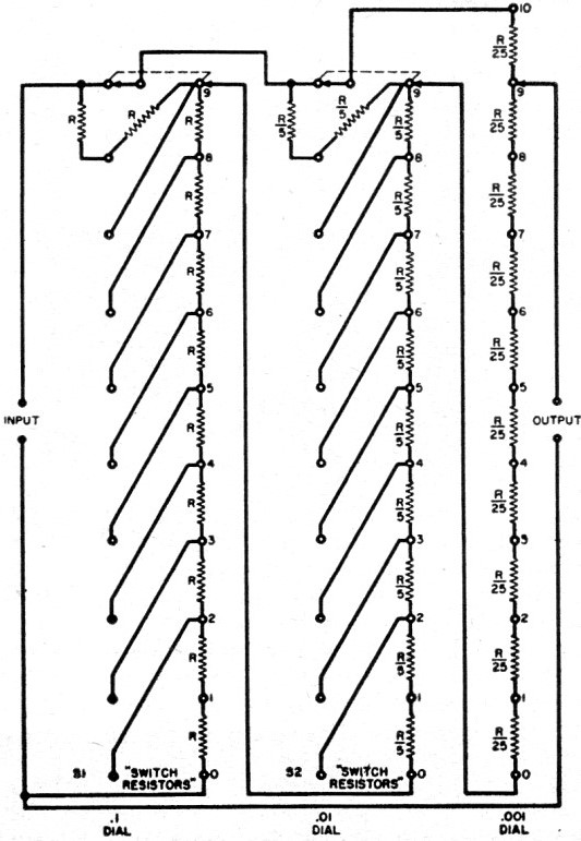
Fig. 3 - This decade unit shows how precision dividers may
be cascaded.
Ingenious wiring, using an inexpensive switch, enables easy construction of a
Thomson-Varley precision divider for use in the service shop.
For calibrating voltmeters, as an attenuator for signal generators, to provide
accurate gain control, or for voltage comparison and amplifier measurements, the
Thomson-Varley divider is hard to beat. This decade voltage divider is functional
and easy to use. Nevertheless, many technicians and engineers have never heard of
this useful circuit. Usually, those who know it do not use it because they think
special unavailable switches are necessary.
Contrary to this widespread belief, the Thomson-Varley divider does not require
esoteric switches or circuit arrangements. It can easily be built around switches
available at even the smallest radio parts jobber.
What is a Thomson-Varley divider? To answer this we must look at attenuators
or voltage dividers in general. The type of attenuator usually found in radio test
equipment, such as audio signal generators and voltage calibrators, is shown in
Fig. 1A.
The attenuator switch, in this circuit, is really a range-setting switch for
the output potentiometer labeled Rp Potentiometer Rp always
varies the output from zero to the highest value permitted by the switch position.
This circuit does not allow precise or accurately known voltage-division ratios.
As can be seen, it is not a decade divider. With a true decade divider, the setting
of any dial does not affect the volts-per-division (or "scale factor," as it is
called) of any other dial.
Someone may do a little thinking and suggest Fig. 1B as a possible decade
divider. For this circuit, the potentiometer Rp would shunt across any
single divider resistor. The output, then, is determined by the voltage drops across
the switch resistors and the potentiometer moving contact to ground.
This is not a practical circuit, however, unless the resistance value of Rp
is at least one hundred times larger than any of the single resistors. Otherwise,
the shunt resistance of Rp would reduce the voltage drop of any switch
resistor that it was connected across. In some applications, Rp would
have to be one thousand times larger than a single switch resistor in order to reduce
the loading to an acceptable value.
True Decade Division
A modification can make this circuit into a true decade divider. We can do this
by making the resistance of Rp exactly equal to one of the switch resistors.
Then, if we have a special switch that substitutes Rp for any single
switch resistor we wish, we have a true decade divider.
If Rp is inserted in place of R1, for example, the voltage
available at the output can be varied, by Rp, from zero to one-tenth
of the input. Substituting for R2, Rp varies the output from
one-tenth to two-tenths of the input, and so on. Unfortunately, this system requires
a switch that is just too complicated to be really practical for widespread use.
Nevertheless, various forms of this type of circuit are sometimes found in special
test circuits.
Varley and Thomson - the latter may be more quickly recognized as Lord Kelvin
- were both men of rare mental agility. They evolved a circuit that provided true
decade voltage division, yet overcame many of the problems involved. However, even
their arrangement generally demands a difficult-to-obtain selector switch. Fortunately,
this final obstacle can be skirted by wiring - and interconnecting a standard two-gang
selector switch. The result is a simple circuit that is relatively easy to wire.
If each vertical row of contacts in Fig. 2 is considered to be one of the
two wafers or poles in the 10-position switch used, the desired simplicity of operation
can be achieved using the common type of switch mentioned plus the few relatively
inexpensive resistors and the potentiometer.
Operation of the Divider
Fig. 2 shows this circuit. As with all Thomson-Varley dividers, there are
eleven resistors in the string of switch resistors. The potentiometer Rp,
at any position of the switch, connects across two of the switch resistors. Of course,
the shunting condition previously noted still exists, but the Thomson-Varley circuit
actually controls this effect and puts it to good use. This is made possible simply
by adding an extra resistor.
Notice, again, that potentiometer Rp connects across two switch resistors
in any position. If we make the value of Rp exactly equal to the resistance
of these two resistors, the total resistance of the divider is 10R. This is true
because a resistance of 2R in parallel with another resistance of 2R is, of course,
equal to R. Thus a drop of one-tenth of the input voltage is developed across Rp
at all times.
This circuit of Fig. 2 is very useful in the shop and laboratory. For example,
if the dial of potentiometer Rp is divided into one hundred divisions,
we can select any portion of the input voltage with a resolution of one thousand
scale divisions!
To show how easy it is to read this type of divider, suppose one hundred volts
is applied to the input. Now, if the switch is set to five and the potentiometer
dial to fifty-six, the output is, very simply, 55.6 volts.
For shop use, the resistors may be 1% deposited-carbon or even selected 5% composition
types. Even a seventy-five cent replacement wirewound control could be used for
the potentiometer Rp. The Thomson-Varley divider, like any other, is
never any better than its components, of course; yet inexpensive components are
quite satisfactory for most shop applications.
Components must be much better for laboratory use. The resistors must be accurate
to 0.1%, or better, and the potentiometer should be a standard laboratory unit or
a multi-turn type. The Helipot brand is representative.
It is important that a multi-turn potentiometer with zero-resistance at zero-setting
be used, otherwise residual output voltages result. For this same reason, in high-accuracy
laboratory applications, switches with very low contact resistance must be used,
since voltage drops across such resistances appear in the output.
For shop use, practically any two-gang switch will do. The Centralab types 1412
and 1413 are suitable. For laboratory applications, laboratory-quality switches,
like those manufactured by Shallcross or Daven, are a must.
To allow adjustment, it may be advantageous to buy a potentiometer of somewhat
higher resistance than necessary. It can then be shunted down to exactly the necessary
value with parallel resistors.
The circuit in Fig. 2 uses a potentiometer for the "second decade." Sometimes,
it is more desirable to use a tapped resistance in this second decade. An instrument
may be needed that divides the output into, say, one part in ten thousand. This
can be done with four decade switches.
Cascaded Dividers
Not many people will ever wish to build a four-decade divider - a three-decade
unit is a more practical project. Fig. 3 shows such a three-decade divider,
which would require the very best of components. Although it would be useful only
in the laboratory, it is educationally important since it shows how Thomson-Varley
dividers can be cascaded.
The resistors in each succeeding decade divider must be exactly one-fifth of
the value of those in the preceding decade. This way, the total resistance of each
decade is always equal to the resistance of two of the resistors in the preceding
decade.
The third decade is conventional. But notice that it has eleven switch positions
and ten resistors. Because the third decade has ten positions, the three decades
can be set to 999 and then one additional step on the last decade adds one to this,
bringing the output to 1000, which is unity. This means the output is equal to the
input and there is no attenuation. The fact that this last switch has eleven positions
is no problem. Eleven-position switches are common. This last divider arrangement
could be used with Fig. 2 in place of the potentiometer. It is simply a matter
of replacing a continuously variable attenuator with a calibrated step attenuator.
The Thomson-Varley decade divider is equally useful for both d.c. and a.c. applications.
Using a value of 1000 ohms for the resistance of R, the circuit of Fig. 2,
when fed with a standard clipped sine wave, makes an excellent voltage calibrator
for the oscilloscope.
Connected to a bank of mercury cells, the decade divider is excellent for calibrating
voltmeters and the like. Since the meter produces a loading error, the value of
R should be lower. One hundred ohms would be an approximate total decade resistance
for this application. The value of R would then be ten ohms.
Test instruments and signal generators need accurate decade attenuators and gain
controls. This responsibility is easily taken care of by a Thomson-Varley divider.
Amplifier gain can be very accurately measured, at all frequencies, with the
Thomson-Varley circuit. It is thus useful for running either frequency-response
curves or making absolute voltage-gain measurements. To check gain, connect a Thomson-Varley
divider to the output of an amplifier or amplifier stage. Then use a single-pole,
double-throw switch to connect the vertical-deflection terminals of an oscilloscope
to either the amplifier input or the divider output.
Now adjust the divider until its output, as shown on the scope, is equal to the
amplifier input. The amount of attenuation required from the divider to exactly
counterbalance the amplifier gain, which can be read easily from the markings on
the divider, gives an accurate picture of the amplifier's gain. Suppose that the
divider at the output of an amplifier stage must be adjusted to one-tenth the voltage
across the entire combination in order to match the input voltage measured at the
grid of' this same stage. This would mean that the stage has a gain of 10.
An advantage of this method of gain measurement is that it is not affected by
irregularities in the response of the oscilloscope, meter, or other device used
to take the measurement, by variation in oscillator output, or by the many other
concealed factors that may introduce errors into the measurement procedure.
The applications noted here are by no means a complete listing. Once the technician
has taken the trouble to build such a divider, he will continue to find additional
uses for it. If desired, the circuit of Fig. 2 can be built into a small aluminum
case for bench use. The cost should be only a few dollars if deposited-carbon resistors
are used.
Posted April 23, 2024
(updated from original post
on 10/2/2014)
|