Antenna Applications in Two-Way Radio Systems |
||
In spite of the proliferation of cellphones and near ubiquitous communications, there are still many applications that require private 2-way communications systems. Emergency services like police, fire, and ambulance; amateur radio, vehicular dispatch for utilities, delivery and repair services; and anywhere that cellular service is not either available or extremely reliable, cannot rely on cellphones for mission critical needs. There are a lot of legacy 2-way radio system antennas and associated towers still being used and many new installations in place. Word has it that use of Citizen Band (CB) radio is on the rise amongst not just truck drivers but everyday drivers and base station operators - largely for the anonymity factor. This article in Radio & TV News gives a good overview of the issues of concern with 2-way radio antennas and towers. Antenna Applications in Two-Way Radio Systems
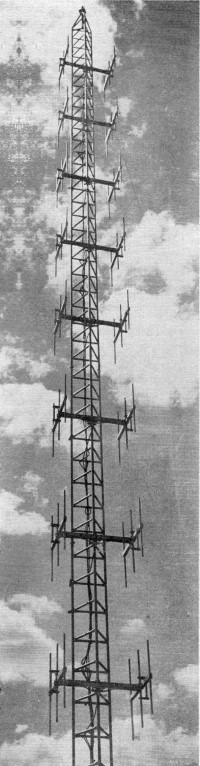
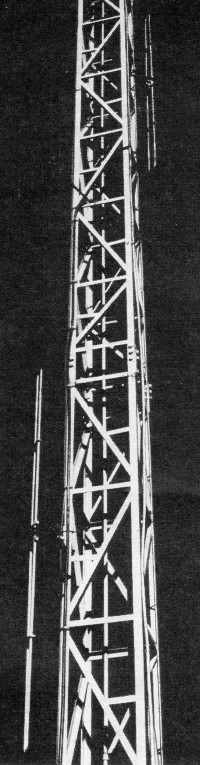
An 8-stack. 48-element array operating in 160-mc. range for a pipeline company in Arabia. All elements are in phase. Total gain is about 17 db over single dipole.
By Tom J. McMullin - Communications Engineering Co. Practical information on performance of directive antennas for mobile radio bands 25-50 mc., 72-76 mc., 148-174 mc. With the growth of two-way radio, greater use is being made of antennas which will improve system performance and and reduce interference. Particularly this true in the 25-50 mc. band where maximum performance is required in the face of growing interference problems due to channel crowding and concentration of activities. In the past several years considerable improvements have been made in transmitting and receiving equipment to help meet this problem. Since the antenna is a most vital part of the two-way system, it too must keep pace with developments and be used where applicable to the requirements. In the mobile two-way radio field, improvement of system performance through use of antennas is limited, for practical reasons, to the base and fixed stations. This discussion will, therefore, be limited to antennas for base and fixed stations in the commonly used bands of 25-50 mc., 72-76 mc., and 148-174 mc. with emphasis on the 25-50 mc. band where most of the systems requiring maximum range operate.
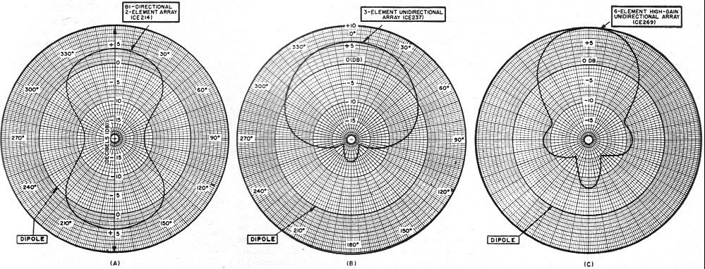
Fig. 1 - Measured horizontal radiation pattern of bi-directional antenna (CE214). Use of Directive Antennas Directive antennas can be used to: 1) improve coverage where the area is not circular in shape or where the base station is not in the center of the area; (2) reduce interference between stations in the same area; and, (3) reduce interference from noise sources which are directional. Where can directive antennas be used to improve base station coverage? Most engineers already are familiar with the use of directive antennas for fixed station point-to-point application such as the remote control of a base station by means of a radio control circuit. Many do not realize, however, that directive antennas have a wide field of application for base station coverage. Radiation patterns of directive antennas are misleading in terms of what the range pattern will be. The usual pattern shown in values of relative power or relative voltage makes the antenna look very directive, which in turn makes the range look attractive in the major lobes and very poor in other directions. The range of a system does not vary directly with the voltage or power of the system. "Line-of-sight" distances can be covered with very low power, while distance beyond the radio horizon require greatly increasing values of power. This factor tends to smooth out the "nulls" and "lobes" of a directive antenna pattern when the pattern is translated into terms of range. Fig. 1 shows the conventional figure-8 pattern of a bi-directional antenna plotted in terms of radiation in relative voltage (inside curve), and the coverage pattern which this becomes (outside curve) when translated into terms of range at antenna height of 200 feet, for a 50-watt mobile unit, 50 mc. talk-back to the station with a signal of 1.5 microvolts at the 50-ohm input of the receiver. Note how the figure-8 voltage pattern is changed to more nearly a rectangular pattern in terms of actual operating range.
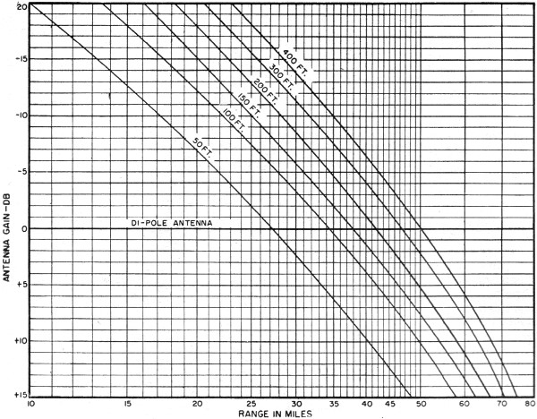
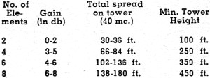
Fig. 2 - Range chart showing effect of base station antenna gains and tower heights. Range patterns for any given directive antenna or combinations of directive antennas similarly can be plotted for given tower height using range charts or range calculators which are available. Fig. 2 is a range chart showing how the range varies with antenna gain respective to a vertical dipole (ground plane or coaxial half-wave radiator) based upon average conditions at 50 mc., for a 50-watt mobile unit talking back to the station with a signal strength input to the station receiver of 1.5. microvolts. On such charts or calculators, decibels (db) is the most convenient form to express the gain since db gain can be easily added or subtracted. If the antenna gain or loss is known at various azimuths, the range can be quickly determined at those azimuths for any given antenna height. Such charts also show the relative gain from using a directive antenna compared to that of more tower height, and indicate where it is economically advantageous to use antenna gain instead of increasing power or using a higher tower. In order to conveniently use available charts and calculators to plot antenna range patterns, it is desirable that the antenna pattern in the horizontal plane be plotted in terms of decibels gain (or loss) with respect to a dipole antenna at the same elevation.
Fig. 3 - Power gain (in db) in the horizontal plane of bi-directional and unidirectional arrays operating at 30-50 mc. Figs. 3A, 3B, and 3C show typical patterns plotted in this manner from data taken on field measurements for: a bi-directional antenna, a 3-element Yagi directional antenna, and a 6-element directional antenna composed of two 3-element Yagis fed in-phase. The 6-element directional antenna can be changed to a bi-directional by reversing directions on one of the 3-element Yagi sections. Its gain in each direction will be somewhat greater than that of the 2-element bi-directional of Fig.3A.
A side of tower mount antenna which gives an essentially omnidirectional pattern. Half-wave folded dipoles fed in phase at fixed distance mounts are attached to opposite legs or sides of tower. Vertical spacing is from three-quarters to a full wavelength center to center. Frequency range is 25-50 mc. A small 450-mc. Yagi antenna with a reflector and 3 directors is also shown near the upper folded dipole. Thus, it can be seen that "range patterns" can be plotted for a directive antenna, a combination of directive antennas, or combination of directive antenna with non-directional antenna for a given frequency range and given antenna height. If the range scale is selected to match a common map scale, the directive antenna or combination of antennas can be selected which will most nearly fit the coverage area outlined on the map. Height of tower can be scaled down or up without materially changing the shape of the pattern - just the size. Stacking for Added Gain In the antenna arrays just discussed most of the gain is obtained by changing the horizontal pattern from a circular configuration. If more gain is desired, and the tower height will warrant the installation, two or more antennas can be vertically stacked. The horizontal pattern shape will remain essentially the same and the added gain will be obtained by compressing the vertical pattern closer to the horizon. The pattern can be broadened by fanning out the stacked antennas with corresponding loss in gain in the maximum direction. In the 150-mc. band, as many as eight 6-element antennas (CE286) can be vertically stacked in a collinear array with a spacing between centers of around one wavelength, fed in-phase, and will have a gain of approximately 17 db over a dipole at the same height. This is the equivalent of increasing the power by over 50 times. On station-to-station contact with directional arrays at each end, the net gain becomes the multiple of the antenna gains at each end. In such a case, gains of around 2500 times in power are practicable. This means lower tower height, less transmitter power, and circuits which would not be possible with a standard type antenna. Directive antennas can also be used in conjunction with non-directive or general coverage antennas to cover a corner or sector of the area not being reached by the general coverage antenna. Maximum efficiency is obtained by bringing down separate antenna leads to separate receivers and switching the transmitter to the desired antenna, automatically muting the receiver not used. At a sacrifice of around 3 db in each antenna, these antennas can be paralleled at the top of the tower and fed in-phase by one cable. The directive antenna should be placed approximately one-half to a full wavelength above or below the non-directive antenna. The vertical separation between the antennas should be such that the near elements are separated by around one-quarter wavelength and in most cases it is desirable that they be fed in-phase. Effect of Noise Although an antenna is a bi-lateral device and works equally well on transmit and receive, certain considerations must be given to ambient electrical noise picked up by the antenna. If the noise is generally distributed throughout 360°, then the signal-to-noise improvement will be comparable to the gain of the antenna. If the noise comes principally from sectors lying outside of the maximum radiation lobes, then the signal-to-noise improvement may be greater than the gain of the antenna. Conversely, if the noise sources lie principally in the beam of the antenna, there may be little or no improvement in signal-to-noise over a non-directional antenna. In planning station installations wherein directional antennas will be used, it is a wise practice to locate the station tower on the side of the city or built-up industrial area where the antenna will not have to shoot over the high noise levels. In checking for noise sources surrounding the proposed tower location, it is also good practice to investigate at further distances in the general direction the antenna will point than would be done for a non-directional antenna. It must be remembered that the gain of the antenna will effectively bring the noise source closer in the same manner that field glasses will bring a visible object closer. Reducing Signal Interference It is apparent that many cases of co-channel interference in the same general area can be reduced by practical application of directional antennas. The greatly increased expansion of radio facilities and the limitation of useful frequencies available point more and more to the future necessity of putting the signal only where it is required. In certain instances, considerable alleviation of skip interference be achieved, although in most cases this is difficult because of conflicting demands of system coverage plus skip interference. In addition to co-channel interference, the effects of interference from transmitter noise, desensitization and intermodulation often can be successfully countered by antenna directivity. In general, a reduction of 7 db is the equivalent of moving the interfering source twice as far away and controlling antenna pattern radiation often is a practical method of reducing a troublesome signal. Side Mounted Antennas
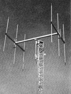
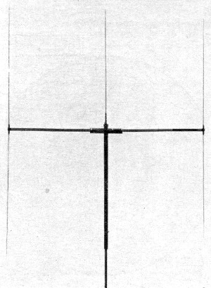
A 6·element unidirectional array operating at 72-76 mc. Consists of two 3-element Yagi antennas one-half wavelength apart and fed in phase. Gain is 10 db over dipole. Matches a 50·ohm coaxial line. At v.h.f. and u.h.f. frequencies commonly used in two-way communications, the only purpose of a high tower is to elevate the antenna above the ground level and extend the radio horizon. A high tower is generally one of the major items of expense, as well as the major "headache" item in installing a system. The increasing difficulties of obtaining suitable quiet locations at reasonable cost around cities with fast growing industrial and residential areas, which are sufficiently removed from airports and airways, have caused a number of users to mount antennas on the sides of existing two-way or broadcast and TV towers. Where the frequencies are compatible, this often is a satisfactory solution and results in greatly reduced capital investment and flexibility if change in location may be required. It also may be a good investment or return on investment for the tower owner, and a number of tower contractors are erecting towers up to 500 feet high for the express purpose of leasing space to two-way users. With modern equipment of good design, stations as close as 500 kc. in frequency can be located on the same tower without interference. At some locations five or more separate systems are located on the same tower with separate antenna systems and are operating without interference. The conventional coaxial or ground plane antenna mounted on a support arm out from the side of the tower is not well suited to such application. Unless properly balanced around the tower, a number of such installations tend to overload the tower and endanger its safety during high wind or heavy icing. Of greater consideration, however, is the strong possibility of upsetting the antenna radiation pattern due to the capacitance and shielding effect offered by the tower structure itself. Quite often an otherwise good antenna will show decided directional effects that are quite unpredictable. To overcome this problem and to simplify installation, antennas have been developed consisting of folded dipoles mounted close into the tower, vertically stacked on opposite sides and fed in phase. The antennas are provided with integral mountings to keep them at a fixed distance from the tower structure. The capacitance of the tower is taken into consideration in the adjustment and matching of the antenna. When these dipoles are mounted on opposite sides of the tower and staggered vertically so that the spacing from center to center is around three-quarter wavelength (near ends separated by at least several feet), the effective horizontal radiation pattern will be very nearly circular. The natural question is, "How does such an antenna perform compared to a ground plane or coaxial half-wave antenna mounted on top of the tower?" Such an antenna is practical only where the tower cross section dimension is less than one-quarter wavelength of the operating frequency. Otherwise, radiation from the dipoles on opposite sides would produce considerable distortion from a circular pattern and we would be back where we started with a standard antenna.
Table 1 - Gains in typical installations. At 150 mc., applications for use of folded dipoles for side-of-tower mounting are limited to relatively small towers - if an omni-directional pattern is desired. If the tower faces exceed approximately 10 inches, out-of-phase components will partially cancel the effective gain. For larger towers this means that only the top of the tower can be utilized - using a pipe extension. If an omni-directional pattern is not required, and coverage primarily is over a 180-degree sector, the half-wave elements can be stacked on the same tower leg, with resultant gain depending on the number of elements employed. In the 25-50 mc. band, tower faces of between two to four feet can be used and this makes available most guyed towers. Table 1 lists the gains to be realized on typical installations compared to a half-wave dipole at the same effective height. If one 180-degree sector is to be favored. then the half-wave folded dipole elements can be stacked in-line on the same tower leg. This will result in up to 3 db additional gain and a corresponding loss over the back 180-degree sector. The side-mount antenna is easy to mount and readily accessible for inspection. It does not clutter up the tower appearance and has minimum effect upon the impedance of an AM broadcast tower. Furthermore, experience has shown that the side-mount antenna is less susceptible to lightning damage and to precipitation static.
A 3-element Yagi unidirectional array composed of coax radiator, director, and reflector. Gain is 6 db over dipole. operates at 33-50 mc. with 50 ohm input impedance. Stainless steel whips are used to reduce vibration fatigue for oil well drilling rig and barge installations. Design of Directive Antennas It is said that there is nothing new under the sun and basically this is true in the design of antennas. The principles of antenna radiation and how to direct and shape that radiation have been known for many years. Basic electrical designs have been developed, all of which perform well under proper applications. The application is important because we know that best performance always can be obtained when the design covers a specific purpose. An antenna which must cover a wide band of frequencies cannot be designed to have as much gain or as a low standing wave ratio as one which must cover only a relatively narrow band. Above all, the electrical design must be selected which will best complement the mechanical design. There is little point in reaching for high gain performance if it will be short lived by certain early failure due to mechanical limitations inherent in the design. In the most simple terms, this means that a good antenna should work well and live long. High gain antennas and arrays can be as reliable as simple half-wave antennas if proper attention is given to the mechanical design. A good mechanical design should have the following characteristics: 1. A high strength-to-weight ratio. Materials and construction should be used which will withstand the force and stress of maximum wind velocities and ice loading to be expected. Light weight means less tower loading and easier erection. 2. Materials which are resistant to the effects of weathering; corrosion, and electrolysis. This applies to the antenna elements, insulation, hardware and mountings. To avoid electrolytic corrosion, metals of widely varying chemical potentials should not be used in direct contact. 3. Insulation should be used only where necessary and then not between high voltage points. It is also desirable to avoid the use of insulating materials at points of high mechanical stress. 4. Plugging of tubular elements to lessen vibration fatigue and fastenings which will not loosen with wind vibration. The small but constant force of wind vibration can be just as damaging as a hurricane if precautions are not taken. Directive and special purpose antennas are now commercially available which have the mechanical and electrical reliability of the simpler dipole antennas commonly used. This makes it possible for system planning engineers to use the techniques of the broadcast service where the radiation is directed and patterned to where it counts-and pays. In the mobile service it pays in terms of improved coverage, shorter towers, and reduced interference to adjacent stations. With a better understanding of their application, it is believed that such antennas will be increasingly used to help meet today's and tomorrow's requirements in two-way radio communications.
Posted February 12, 2021 |
||