|
April 1948 Radio News
 [Table of Contents] [Table of Contents]
Wax nostalgic about and learn from the history of early
electronics. See articles from
Radio & Television News, published 1919-1959. All copyrights hereby
acknowledged.
|
The APS-42, as described in this 1948 issue of
Radio News magazine, was truly a
break-through x-band airborne
search radar system born out of the lessons learned from its predecessor: the
APS-10 search radar developed during World War II. This very compact radar
system is contained within a volume of about 3 feet on a side (not including the
cockpit controls and displays. The close proximity of the receiver front-end to
the antenna made for a very low noise figure and, consequently, high
sensitivity. Interestingly, there is not a whole lot of information available on
the Internet for either radar. In fact, this article is probably the most
information source available on the APS-42.
The APS-42 Radar
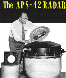
Transmitter-receiver and antenna are carried in this pressurized
container made of spun magnesium and laminated fiber glass. Single cable connects
unit to scope shown at left.
Design and operational features of a new type radar unit. It is compact, light
in weight, and excels all other airborne equipment.
By L. W. Mallach
Project Eng., The Houston Corp.
This outfit doubles the range of the well-known wartime APS-10. It weighs only
115 pounds, involves only two units, and for flexibility of operation surpasses
any radar yet airborne. It is an X-band navigational radar equipment complete within
itself, and provides radar mapping, responder beacon operations, obstacle detection,
and weather mapping. The Army Air Forces call it the AN/APS-42 (XA-2). It is intended
for service in both military and commercial aircraft, preferably in a chin or belly
location. In both positions it will furnish a nominal 360° scan.
For mapping, the equipment supplies an approximate cosecant-squared pattern from
the antenna, for use in mapping areas adjacent to the path of flight, to show contours
and type of terrain traversed.
In responder beacon operation, it transmits a 2.2 microsecond pulse and receives
on a frequency of 9310 megacycles, with automatic frequency control for picking
up signals from transponder type beacons operating in this band. The antenna utilizes
a cosecant-squared pattern for beacon operation to minimize any differences in altitude
of the aircraft or angle of flight while triggering and receiving a beacon.
For obstacle detection, this radar transmits a pencil beam approximately six
degrees vertically and horizontally in the approximate plane of the aircraft. This
is useful for detecting the position of any reflected object within the swept pattern,
particularly mountains and other aircraft.
Of considerable importance, too, is the fact that the equipment also may be used
for detecting areas of heavy moisture content and the accompanying turbulent areas
with which they may be associated. For this service, a 2.2 microsecond pulse with
a pencil beam is transmitted.

Top view of transmitter-receiver. Gyroscope and motors keep unit
approximately level during flight.
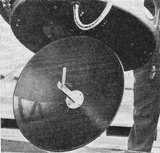
Signals and echoes flow out and in through this short radar antenna
and parabolic reflector.
Of the two experimental units completed, one has gone to the All Weather Flying
Squadron, the other to the Aircraft Radio Laboratory - both at Wright Field - for
in-service testing. A total of 107 production units now are being manufactured for
the Navy, for assignment to planes flown by NATS.
Tests so far indicate substantial fulfillment of the design objectives for transport-type
radar navigation equipment. Problems involved consisted basically of evaluating
the functions of wartime airborne radar which would seem more useful for air transport
uses.
Among the functions studied were the bombing type radar's ability to map large
land areas, the fighter radar's ability to detect other aircraft in the vicinity,
and the paratrooper's radar equipment used for beacon navigation and more-or-less
precise navigation of uncharted areas.
In looking over the field of wartime equipment, it became evident that the radar
best suited for commercial use was the APS-10. But serious disadvantages were inherent.
Accordingly, it was decided to utilize basic design, and add other desirable radar
features, together with operational simplification and antenna stabilization.
Final design, as evolved by The Houston Corporation on AAF contract, includes
these principal features; low over-all weight; compactness; flexibility of operation,
as noted in the first paragraph; higher power, in order to achieve the results mentioned
more easily; stabilization of the antenna to present a better picture regardless
of aircraft attitude; simplicity of operation requiring a minimum of pilot-operated
controls, and reliability of operation over long periods of time by simplification
of adjustments and components.
To accomplish these features, the equipment was designed so that the radar transmitter-receiver
and antenna were mounted in one spherical package measuring 33 inches in diameter
and 36 inches over-all height. Such a package or unit is suitable for either belly
or chin mounting with approximately 21 inches of the cylinder protruding below the
aircraft skin with antenna enclosed. This unit is stabilized by an internal arrangement
so that the antenna is mounted on gimbal rings with servos providing automatic stabilization
for 25 degrees either direction in roll and 20 degrees in pitch.
Inasmuch as the transmitter-receiver is mounted directly over the antenna, the
maximum electrical efficiency is achieved through the shortening of the connecting
cables. All components required for the operation of the transmitter-receiver-antenna
are stabilized and mounted within this package, which is also pressurized by an
integral air pressure pump actuated by an automatic pressure switch. By this means,
the entire assembly is maintained at sea level pressure up to 30,000 feet, thus
providing a minimum of disturbances from high voltage discharges or other high altitude
phenomena.
The indicator employed is a standard 7-inch type cathode-ray tube using a PPI
type display. This display is, in effect, a polar coordinate map of surrounding
area, with the plane's position being in the center of the tube and the relative
angle to other objects being indicated by the angle in degrees from the top of the
tube, the top being the straight-ahead direction.
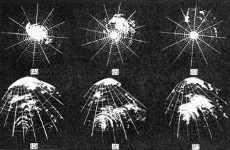
Pictures (A. B. and C.) of a hurricane on a radar unit which scans
complete circle around the station instead of merely an area in anyone direction.
as shown in D. E. and F. The storm (A) appears as a great white blob on the radar
scope as the hurricane passes almost directly overhead. As the clouds travel northeast
(B), the image moves from the center of the scope. In picture C only wisps of clouds
remain as the hurricane moves away. Pictures D. E. and F. taken on another type
of radar, were made from Army station near Orlando, Florida. In picture D, the center
of the storm, at lower left, is bordered by hazy concentric arcs. These are line
squalls. Above them other hazy spots are masses of rain clouds. In pictures E and
F the hurricane comes closer. Position of radar unit is in the bright area at the
top of the photograph.
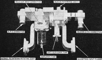
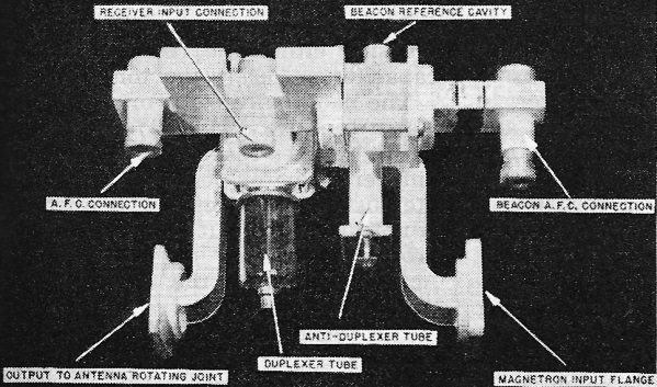
Electroform wave guide mixer (duplexer assembly).
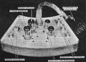
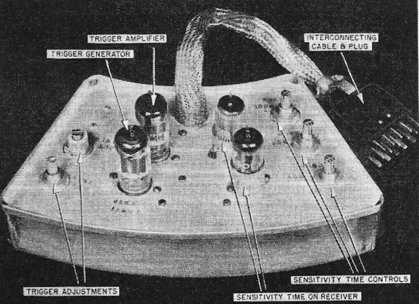
Trigger generator and sensitivity time control.
In order to simplify the operation and make it suitable for the pilot to handle
his own radar equipment with a minimum of effort, several controls are mounted on
the indicator.
1. A combination "on-off" and "range" switch. In the maximum counter-clockwise
position the equipment is "off," while moving the switch to any range position turns
the equipment "on." Subsequent operation is automatic after an initial three-minute
warm-up time-delay period. The ranges provided are 5, 15, 50, and 150 nautical miles,
with five evenly spaced range marks on each range, together with "range-in-use"
lights above the indicator tube.
2. A "function switch." This provides for the versatility of operation of the
equipment. The first position is "mapping," which provides for a radiated beam known
as cosecant-squared or equal energy; and, as its name implies, it distributes an
equal amount of transmitted power to the ground in the immediate vicinity of the
ship as well as at the horizon. Therefore, all of the ground contour from immediately
ahead of the plane to the horizon is reproduced on the indicator, as a contour map
of the surrounding area.
In the next position, "obstacle detection," the antenna pattern is a very narrow
or pencil shape beam which is approximately 6 degrees in width in the vertical direction.
The beam is useful for detecting any obstacle, either other aircraft in flight or
high ground obstacles, such as a mountain range projecting into the path of the
aircraft in flight. By eliminating the reflections from the ground in the vicinity
of the aircraft, such as are obtained on the equal energy path, it. then becomes
possible to see only those objects projecting into the flight path of the aircraft.
The third position is for "beacon operation" and it provides for the interrogation
of ground radar beacons. These ground radar beacons have been established by the
Army, Navy, and Coast Guard at various well-known geographical locations. It is
possible for the radar to interrogate them so that they in turn show a signal on
the indicator, which is suitably coded to indicate the beacon station identification
and at the same time provide an accurate measure of azimuth and range to the particular
beacon. Thus, precise navigation is possible through beacon operation.
The fourth position is for use in obtaining "weather information." Probably one
of the most valuable assets of the transport radar is its ability to observe weather
phenomena. By utilizing a pencil type of beam and tipping the antenna upwards to
eliminate any reflection from the ground, it is possible to search the sky for heavy
rain-bearing clouds, thunderstorms, and areas of super-cooled water. These manifest
themselves by peculiar displays on the indicator which are easily recognized by
an observer with practice. It is thus possible for transport aircraft to avoid such
areas of possible danger. It is also possible, by mapping such areas by radar, to
pick the narrowest or "softest" spot, if indeed it is not possible to avoid the
weather altogether. Also, by searching in layers in a vertical direction, it is
quite possible to find layers where a minimum of weather disturbances prevail so
that flight altitudes may be changed to take advantage of such a situation.
The other controls to be operated by the pilot are (3) a receiver sensitivity
control which, as its name implies, governs the sensitivity and hence the signal
indication on the indicator. An intensity control (4) is used for governing the
intensity of the display on the indicator tube primarily for adjustment under different
cockpit lighting conditions. Lastly, there is a (5) trim control, which provides
arbitrary displacement of the center of stabilization on the pitch axis over a range
of plus or minus 7 1/2 degrees.
Operation of APS-42 is similar to all centimeter type radar equipment, in that
it transmits a high power pulse of very short duration through a waveguide assembly
to an antenna which focuses the energy to a very narrow beam and rotates the beam
in azimuth. Timing of the transmitted pulse is very precise, and the time required
for the transmitted pulse to be sent out and reflected from a target is so measured
by the equipment that the distances are recorded with good accuracy. Received echoes
are picked up by the same antenna assembly, and fed into the same waveguide assembly,
separation taking place at the mixer unit so that the receiver is isolated from
the transmitter, meaning that a common antenna-waveguide assembly is used for both
transmission and reception.
Signals and other radar indications appear on a circular tube face in the conventional
PPI pattern such that the zero azimuth position on top of the tube represents straight
ahead, and the other azimuth positions are calibrated in a 360-degree interval around
the top. Since the antenna rotates constantly, it furnishes a complete azimuth picture
at all times, which continues to change as the aircraft moves. The various functions
of the equipment are obtained by combinations of changes to the radar characteristics,
particularly the transmitting characteristics. For instance, in switching from "search"
to "weather," the transmitter pulse is lengthened by a factor of approximately three.
In switching from "search" to "beacon," the transmitter pulse is likewise increased,
and at the same time, the transmitted antenna pattern as well as the received antenna
pattern is changed from a narrow vertical beam: to abroad vertical beam, and the
receiver frequency is shifted approximately 50 megacycles
The antenna system consists of an 18-inch diameter parabolic reflector with a
double dipole radiator located at the focal point of the parabola and fed from a
standard X-band waveguide. In addition, a double parasitic dipole is located on
top of the antenna feed, and immediately behind the normal dipole radiators. This
parasitic dipole is arranged in such a manner that it can be actuated so that its
dipoles are parallel to, and therefore parasitic to the radiating dipoles. The parasitic
dipoles are free to rotate 90 degrees, so that they are then 90 degrees with respect
to the radiating dipoles and their effect is negligible. It is by the use of such
an arrangement at the frequency of 9375 megacycles that it is possible to focus
nearly all the energy radiated into a very narrow beam. The beam will be approximately
six degrees wide in the horizontal and vertical dimensions at the half-power points.
This energy, by reason of the dipoles' horizontal position, is horizontally polarized
- the most effective type of polarization on search type radar for use in detecting
land and sea targets. It is also necessary that the energy be horizontally polarized
for beacon operation, as the beacon antennas themselves are horizontally polarized.
When the parasitic dipole arrangement is used, a certain amount
of the radiated energy is deflected downward toward the earth's surface so that
there is, in effect, what amounts to a cosecant-square pattern of radiated energy.
The parasitic dipoles are tilted slightly with respect to the axis so that they
can radiate in a downward direction. Being located in the path of the energy being
reflected to the parabolic reflector, they absorb and reradiate a certain amount
of the distributed energy, and are, therefore, actually spoilers in the radiated
field of the antenna.
Because it is necessary to place the parasitic dipoles in two positions, they
may be turned 90 degrees against a spring by gears connecting to the antenna drive
motor. The spring re-turns them to the non-radiating position when the power is
turned off.
The antenna is mounted directly below the chassis containing the transmitter-receiver
components, and is supported by a fork-type casting. Since the transmitter is fixed
and the antenna rotates, a rotating joint has been arranged to transfer the energy
from the magnetron transmitter to the antenna, with no change in the transmission
characteristics. The antenna is driven by a 400-cycle induction motor which operates
at a normal speed of 7200 r.p.m., and which is reduced by a gear train to a normal
antenna rotation of 30 r.p.m.
Since not everyone in the aviation industry thinks alike it is possible that
the transport industry may require modifications of this equipment, one of which
might be the substitution of a 5-inch indicator, due to severe cockpit space limitations.
This modification is easily accomplished and, in fact, the equipment can be operated
with such an indicator, with an external control box located for easy access by
the pilot. It is also probable that many of the later design aircraft are better
suited to a nose installation, rather than to tolerate the drag occasioned by a
belly installation, even though the nose installation reduces the radar coverage
in the aft direction. The physical size of this particular unit would prohibit its
installation in most of the nose areas available, but suitable modifications can
be made to accomplish this. The equipment is normally able to operate with two indicators
and a third could be provided, should it be required, for navigator's use.
Combining the several achievements in a single lightweight assembly has been
no easy task. Now that the services have underwritten its early development, I believe
the design can be produced within the economic range of the air transport industry.
Coming tests by the storm-searchers, radio experts, and transport fliers should
demonstrate the value of such many-in-one equipment.
Posted May 31, 2022
|