Basic Electronic Counting |
||
Forgive me if I sound like a broken record (a scratched record, actually), but when selecting articles for posting here on RF Cafe, I like to include ones that are directed toward newcomers to the field of electronics as well as for seasoned veterans. This piece from a 1958 issue of Radio & TV News magazine entitled "Basic Electronic Counting," is a prime example in that it introduces the concept of binary numbers. We've all been there at some point in our careers. A big difference between now and when this article appeared is that in 1958, almost nobody was familiar to binary numbers, and fuggetabout [sic] octal and hexadecimal. Only those relatively few people designing and working with multimillion dollar, vacuum tube-based digital computers installed in universities, megacorporations, and government research facilities had ever dealt with digital numbers. The earliest example of powers of two I remember was back in junior high school. It had to do with a riddle asking whether you would rather take a month-long job that paid $1,000, or work the same time getting paid by the day beginning at 1¢ and then having your pay doubled for each day worked (noncumulative). I was probably dumb enough to say I'll take the $1,000, but the smart kids in the class would have, correctly, opted for the pay doubling scheme: 1¢ 230 = $10,737418.24 And of course there's the joke that goes: There are only10 kind of people in the world - those who are familiar with binary numbers and those who aren't. Basic Electronic Counting
Northwestern Television & Electronics Institute A technician's introduction to binary notation, an important digital technique in computer work. At one time, binary numbers were relegated to an obscure little corner in the basement of mathematics and were of concern only to a few cloistered mathematicians whose interest in such numbers was largely academic. Today, the binary numbering system is used extensively in computers, electronic counters, and automation equipment. In the decimal numbering system, each digit of a number may have any of ten different values: 0, 1, 2, 3, 4, 5, 6, 7, 8, or 9. For example, 743,297 is a number expressed in the decimal system. In the binary numbering system, each digit of a number may have either of two values: 0 or 1. For example, 1101011110 is a number expressed in binary notation. Editor's Note: With the mushroom growth of computer technology, there has been a continuing demand for qualified personnel in this field on all levels. Unfortunately, of the meager sources of information in this area, most are quite specialized or on an advanced technical level. This article is a straightforward treatment of a system of counting, different from the one with which we are familiar, that has become a basic digital technique. it is used because it happens to suit those electronic circuits that can be adapted to counting. The basic counting circuit is also indicated. Are you interested in more articles of this type? Let us hear from you.
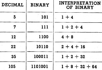
Table 1 - The binary equivalent of any decimal number is expressed as a series of "ones" and "zeros." as explained in text. with each "one" representing a given value according to its position. For illustration. several decimal numbers are given here with binary equivalents. showing derivation of the latter.
Fig. 1 - In the flip-flop circuit, one tube is cut off while the other is conducting. Each pulse applied to the input reverses the circuit. When the circuit is in the "zero" condition (left tube cut off and right conducting), the neon light is off. The light comes on when the circuit is switched to the "one" condition.
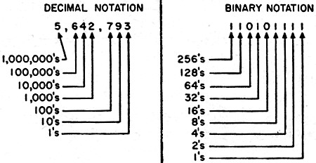
Fig. 2 - In decimal notation (left), the digits represent. from right to left, ones, tens, hundreds, thousands, etc. In binary notation (right), the digits represent from right to left, one, two, four, eight, sixteen, etc. The decimal equivalent of the binary number shown to the right is the sum of the quantities represented by the ones, which, in this case, total 431.
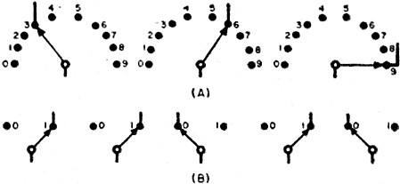
Fig. 3 - By setting up switches in groups, it is possible to use them for representing and recording either decimal or binary numbers. However, in the case of decimal notation (A), observe that each switch would have to have ten positions. In the case of binary notation (B), on the other hand, the switches are much simpler, each one requiring only two positions. The switches in (A) are set to represent the decimal number 369. The switches in (B) are set to represent the binary number 11010, equivalent to decimal number 26.
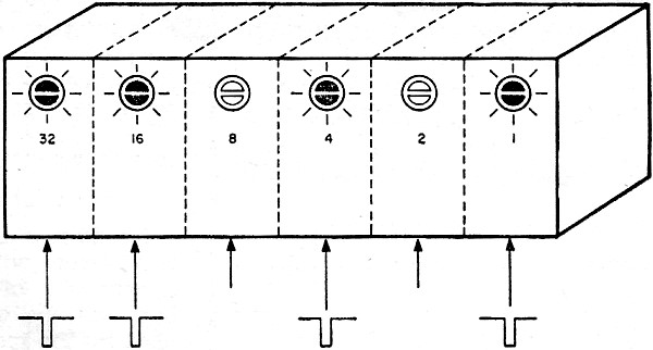
Fig. 4 - A binary number may be stored in a series of flip-flop stages. The binary number 110101 (1 plus 4 plus 16 plus 32) is stored in the six flip-flops indicated. The assigned values of the neon bulbs that are lit add up to the decimal number 53. Numbers are recorded and stored by feeding pulses to appropriate stages. In the decimal system, the relative positions of the digits determine the value of a number. The right-hand digit represents "ones," the next digit to the left represents "tens," the next digit represents "hundreds," the next "thousands," etc. The decimal number 4632 therefore means 4 thousands, 6 hundreds, 3 tens, and 2 ones. In binary notation, the relative positions of the digits also determine the value of a number. The right-hand digit represents "ones," the next digit to the left represents "twos," the next digit represents "fours," the next "eights," etc. The value of each position is double that of the position to the immediate right. The binary number 10111 therefore means sixteen and four and two and one. This system of positional values is illustrated in Fig. 2. The binary equivalents of several decimal numbers are given in Table 1, for illustration. In any machine used for counting or computing, each digit of a number is represented by a circuit or component. Fig. 3 shows how a group of switches, for example, can be used to represent either decimal or binary numbers. When the numbers are to be expressed in decimal notation, each switch (or circuit) must be able to represent any of ten different conditions, as in Fig. 3A. When binary notation is used, however, each switch (or circuit) need be capable of representing only two different conditions, as in Fig. 3B. The resulting simplicity of the required circuitry is the reason for preference of binary notation in computing and counting devices. Some computers are designed to work with decimal numbers, but even in these machines each digit of the decimal number is usually represented by its binary equivalent. Manually operated switches like those shown in Fig. 3 are not often used in practice, because it is desirable to make the operation of the circuit as nearly automatic as possible. Relays and stepping switches are use only sparingly because they cannot operate at the speeds normally required. Each switch shown in Fig. 3 would therefore be replaced by an electronic circuit. A circuit to replace each ten-position switch shown in Fig. 3A would require ten tubes (with some refinements, the number of tubes could be reduced). Each binary switch of Fig. 3B however, could be replaced by a circuit using only one double triode. This circuit, the flip-flop, is shown in Fig. 1. This same circuit is sometimes referred to as a binary scaler, bi-stable multivibrator, or Eccles-Jordan circuit. Like the two-position switch which it replaces, the flip-flop circuit has two conditions: off and on. When the left-hand triode is cut off and the right-hand triode is conducting, the circuit is said to be in the off or zero condition. When the circuit is in the opposite state - left-hand tube conducting and right-hand tube cut off - it is said to be in the on or one condition. In many types of instruments, it is necessary to determine (without removing the instrument from its case) whether the flip-flop is in the zero condition or the one condition. For this purpose, a small neon indicator is mounted on the panel of the instrument and connected in the circuit as shown in Fig. 1. When the circuit is in the zero condition, the left-hand tube will be cut off and the neon lamp will be dark. However, when the circuit is in the one condition, the left-hand tube will be conducting and the neon lamp will glow. In the flip-flop circuit shown in Fig. 1, each plate is coupled, through a resistor, to the opposite grid. It is for this reason that one tube will conduct when the other tube is cut off. If, for example, the left-hand tube is cut off, its plate voltage will be high. This high voltage, applied through the coupling resistor to the grid of the right-hand tube, causes the right-hand tube to conduct. If a negative pulse is now applied to the input, the right-hand grid will be driven to cut-off and the plate voltage of this tube will rise. This increase of voltage, applied through the coupling resistor, will now cause the left-hand tube to conduct. The circuit therefore reverses its condition each time it receives an input pulse. If the circuit is in the zero condition at the start, it will switch to the one condition when an input pulse is applied. A second input pulse will switch it back to the zero condition, a third input pulse switches it to the one condition again, and so on. The circuit is quite similar to the cathode-coupled multivibrator used as the vertical or horizontal oscillator in many television receivers. In such sets, however, components are chosen to provide time constants that will alternately cause each of the triode sections to cut off and conduct, even when no pulse is applied. Thus, a free-running oscillator is obtained whose frequency depends on the time constants chosen. In the flip-flop circuits used for counting, the triodes retain their condition of cut-off or conduction until they are signaled to change by an input pulse. It is apparent that a group of circuits like the single one shown in Fig. 1 can be used to represent a binary number. For example, the binary number 1011 can be represented (stored) in a group of four flip-flops with the first, second, and fourth circuits in the one condition, and the third circuit in the zero condition. (The first circuit corresponds to the right-hand digit of the binary number.) In computer work, a group or bank of flip-flop stages is known as a resister. The bank of six flip-flop stages shown in Fig. 4 can be used to store any binary number from 000000 to 111111. The six neon lamps in these circuits can be used to indicate the decimal equivalent of the binary number stored. This is accomplished by assigning a value to each light. These values are often printed on the panel of the instrument as shown in Fig. 4. The lights, starting with the first circuit, are assigned values of 1, 2, 4, 8, 16, and 32. The decimal equivalent of the binary number stored in the flip-flops is determined by adding up the assigned values of the lights that are on. For example, if the binary number 110101 is to be stored in the flip-flops, an input pulse would be applied to the first, third, fifth, and sixth stages, assuming that all stages started in the zero condition. The lights in these stages will now be on and their assigned values (1, 4, 16, and 32) add up to 53, which is the decimal equivalent for binary number 110101.
Posted November 18, 2019 |
||