|
This article describes
a method for tuning beam antennas from the ground rather than needing to experiment
with matching capacitors and/or inductors at the antenna end of the transmission
line. The scheme uses a separate length of transmission line attached to the reflector
element at a length an integer number of half-wavelengths as required to reach the
ground. That way, tuning elements can be installed and adjusted for one or more
bands without needing to climb up to the antenna. The method can be used for any
number of elements, but of course it could get a bit messy with more than a couple.
The author, Major Charles E. Spitz (W7JHS), describes using a field strength meter
to verify tuning correctness. Having read many QST magazine articles on
antennas over the past decade or so, I don't recall ever seeing this technique presented.
A New Approach to Beam Antennas
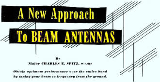 By Major Charles E. Spitz, W7JHS By Major Charles E. Spitz, W7JHS
Obtain optimum performance over the entire band by tuning your beam to frequency
from the ground.
The amateur who erects a beam antenna is usually prepared for a lot of cut and
try, and it takes it. Perhaps he copies or buys a commercial beam. The service technician
buys a commercial beam for that FM or TV installation simply because he doesn't
have time to fuss with it. The purpose of this article is not to deride the manufactured
products. There are good assemblies available, but to illustrate the difficult nature
of beam antenna installations and the fact that the process of tuning can be readily
solved by the use of a simple method.

Fig. 1 - "Lazy H" antenna - feedlines go to X.

Fig. 2 - (A) and (B) are conventional beams. Tuning method described
is shown in (C).
After experimenting for some time with the described system, the author has achieved
results that more than came up to expectations, and possibilities seem to be unlimited.
Consider first a simple dipole and reflector. The radiator is usually cut for
frequency and left at that length. Not so the reflector, however, as considerable
adjusting must be done for either maximum forward gain, or front-to-back ratio at
a particular frequency. Many surplus telephones have been pressed into service as
a necessary aid.
It's a two-man job to adjust a receiving beam, and a three-man job for transmitting
- someone has to carry the field-strength meter! If the antenna is out of reach
when finally installed, as many are, a derrick is a mighty handy accessory. Most
people tune on the ground and then just hope it stays that way when the antenna
gets into position.
Look at Fig. 2. The classical method of adjustment is to slide small tubing ends
into a larger diameter main piece, as in A. In B, tuning is accomplished by a small
stub of a few inches and is the usual method for wire. It will be seen that the
method in C is essentially that of B, in that the stub L can be tuned remotely (in
effect) if the reflector feedline is tuned from a position any number of half-waves
longer.
Tuning a reflector with this system of parasitic excitation means there are standing
waves on the reflector feedline; however, several experimental feedline lengths
of fifty feet and beyond did not indicate excessive losses by virtue of increased
lengths.
The antenna used in the tests, the results of which are shown in the graphs,
consists of a radiator composed of four half-waves in-phase, two elements stacked
above two, and is popularly known as the "Lazy H." A similar curtain was placed
one quarter-wave behind. It will be noted that the feedlines between the upper and
lower elements are not transposed, being phased by center feeding, and present a
load impedance of about 70 ohms. The resultant broadband characteristic is easily
seen in the graphs. For those who may be unfamiliar with the antenna, it is shown
in Fig. 1.
Another advantage of remote reflector tuning is the fact that it may be tuned
to any frequency, within reasonable limits, by simply turning a condenser dial at
the equipment. This should be a major aid to the e.c.o. enthusiast, as well as valuable
in conjunction with FM or TV channel selection.
Feedlines used in the tests were RG-11/U and RG-8/U coaxial cable with little
differences noted. A field-strength meter and a folded dipole were set up 300 feet
from the antenna, and with a remote meter at the operating position and the reflector
tuned for maximum forward signal, the meter was set so that zero on the graph indicated
a maximum signal with 100 watts of r.f. power. A Model MM2 "Micromatch" was used
to monitor power level and to keep a check on standing-wave ratios. A condenser
dial reading of 100 indicated 570 μμfd. (two sections of 285 in parallel)
and zero for minimum capacity.
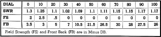
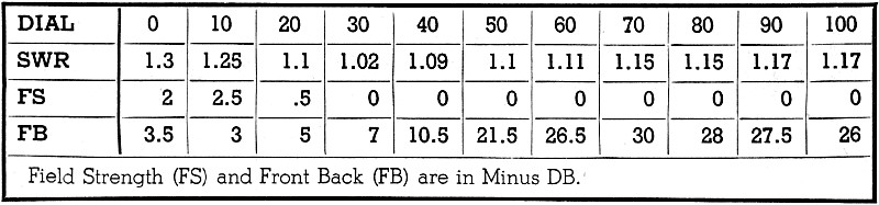
Table 1 - Performance characteristics of the antenna described,
measured at 28.5 mc.
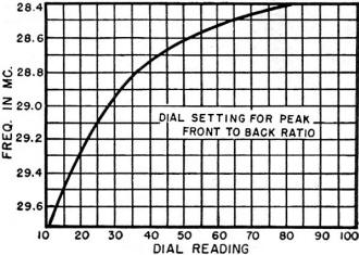
Fig. 3 - Condenser settings for reflector tuning to give maximum
front-to-back ratio.
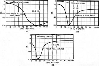
Fig. 4 - Measurements of front-to-back ratio for three different
frequencies, as the reflector tuning condenser is varied through its range. A tuned
55 foot coaxial feeder was used on the reflector for these tests. Due to limitations
in the measuring equipment the performance figures below minus 26 db. were calcu
lated on the basis of over-the-air reports.
The graphs A, B, and C of Fig. 4 illustrate the field-strength and front-to-back
ratios at all positions of condenser tuning at the frequencies of 28.5, 29 and 29.5
megacycles with a 55-foot coaxial feedline from the reflector. Accurate measurements
were not possible beyond -26 db., and the -30 db. measurements were filled in by
over-the-air reports.
Fig. 3 shows an example of the utility of reflector tuning. A check was made
for the point of maximum front-to-back ratio every 100 kc. from 29.7 to 28.4 mc.,
and with the aid of the graph, tuning could be set at any time at the best position
for the operating frequency in use.
As may be surmised, tuning the reflector affects the standing-wave ratio of the
radiator feedline by changing the antenna impedance, and the effect is noted in
Table 1; however, readings of forward gain indicated little field-strength loss
for ratio orders of 2 to 1.
Coverages of the frequencies 27,150 to 28,500 kc. was accomplished by use of
a fifty-foot feedline. Actually a fifty-foot feedline is used with a five-foot extension
plugged in for the 28.4 to 29.7 mc. range, since it was felt that introducing such
variables as tuned coils would unnecessarily complicate the system.
You may note that all discussions have referred to field-strength readings and
wonder about receiving capabilities. It was noted that receiving checks in the amateur
band were difficult to make due to fading, which would not occur in local FM or
TV areas for such reception. An interesting application came to light, however,
when the author was requested by KZ5AZ, who was visiting, to hook up with a Canal
Zone station, so that he could talk to his wife. The antenna was swung in that general
direction on a crowded weekend. W6 and W7 signals were pouring through by the hundreds,
so as each signal was tuned in, the condenser was turned until the signal dipped
or rose to indicate a southeastern signal. In that manner of DF-ing, five signals
were quickly selected, three turning out to be Puerto Ricans, and, two in the Canal
Zone, one of which, KZ5CJ (a few houses from KZ5AZ's home QTH), was quickly raised
and all in a matter of a few minutes!
The coaxial feedline to the balanced antenna proved poor in receiving discrimination.
However a two-wire coaxial cable such as RG-22/U should improve receiving performance
considerably, and in some installations molded parallel lines, provided impedances
are matched, might be suitable.
The business of trimming the reflector feedline for a desired frequency and band
may bother you; however, it is suggested that whatever feedline length seems readily
available be tried. If the results are not satisfactory, then the feedline may be
added to until the proper frequency is reached within tuning range. This is not
so difficult as it might seem, as at high frequencies the transmission-line velocity
factor is taken into account. With a factor of 0.66 for coaxial cable, on ten meters
a half-wave becomes about ten feet, and any tuning range within that band could
be covered within any portion of it as an added length. A larger tuning condenser
than that used, in order to obtain a greater bandwidth, could not be employed, as
at maximum capacity the impedance becomes so low as to be the equivalent of a short
circuit. Double the capacity was tried and was of no value, simply making tuning
at minimum capacity critical.
The value of reflector tuning may be questioned by some who wonder about the
small forward gain changes indicated. It was mentioned that a broadband antenna
was used in these checks which the curves bear out. A close spaced parasitic or
Yagi antenna, being of a much higher Q should exhibit a distinct curve about the
forward line. Where a broadband antenna is in use, tuning the reflector should be
of value in reducing interference, BCI, or TVI, and for all reception, short-wave,
amateur, FM, and TV it should increase external signal-to-noise ratios.
Some thought was given to the use of a phasing section between two elements or
curtains of an array, and tests were made. The results were poor, however, since
at the reflector the direct wave, when off frequency, exhibited a phase difference
to the radiated wave, and unless the spacing between the elements was also variable,
the bandwidth would be limited. This effect would be aggravated by a low transmission
line velocity factor.
What about tuning all parasitic elements, such as directors, etc.? What about
arrangements to steer radiation angles? The author has given some thought to these
problems and is conducting further experiments. The sky seems to be the limit in
tuning parasitic elements, and it surely seems that the manually-tuned beam is on
the way out.
Acknowledgement must be made here of the patience and valued assistance of Lynn
Mutrix, W5O1X; Captain Bascom E. Tillotson, W5PDW; Chief Warrant Officer Chester
B. Harmon, WOJG; Reynold B. Champagne, W4KQW; and the many others whose observations
aided the work.
Posted February 20, 2020
|