Electronics World articles Popular Electronics articles QST articles Radio & TV News articles Radio-Craft articles Radio-Electronics articles Short Wave Craft articles Wireless World articles Google Search of RF Cafe website Sitemap Electronics Equations Mathematics Equations Equations physics Manufacturers & distributors LinkedIn Crosswords Engineering Humor Kirt's Cogitations RF Engineering Quizzes Notable Quotes Calculators Education Engineering Magazine Articles Engineering software RF Cafe Archives Magazine Sponsor RF Cafe Sponsor Links Saturday Evening Post NEETS EW Radar Handbook Microwave Museum About RF Cafe Aegis Power Systems Alliance Test Equipment Centric RF Empower RF ISOTEC Reactel RF Connector Technology San Francisco Circuits Anritsu Amplifier Solutions Anatech Electronics Axiom Test Equipment Conduct RF Copper Mountain Technologies Exodus Advanced Communications Innovative Power Products KR Filters LadyBug Technologies Rigol TotalTemp Technologies Werbel Microwave Windfreak Technologies Wireless Telecom Group Withwave RF Cafe Software Resources Vintage Magazines RF Cafe Software WhoIs entry for RF Cafe.com Thank you for visiting RF Cafe!
ConductRF Phased Matched RF Cables - RF Cafe

Innovative Power Products Passive RF Products - RF Cafe

Temwell Filters

Please Support RF Cafe by purchasing my  ridiculously low-priced products, all of which I created.

RF Cascade Workbook for Excel

RF & Electronics Symbols for Visio

RF & Electronics Symbols for Office

RF & Electronics Stencils for Visio

RF Workbench

T-Shirts, Mugs, Cups, Ball Caps, Mouse Pads

These Are Available for Free

Espresso Engineering Workbook™

Smith Chart™ for Excel

Crane Aerospace Electronics Microwave Solutions: Space Qualified Passive Products

Constant K Type High-Pass Filter Design
August 1952 Radio News

August 1952 Radio & Television News
August 1952 Radio & Television News Cover - RF Cafe[Table of Contents]

Wax nostalgic about and learn from the history of early electronics. See articles from Radio & Television News, published 1919-1959. All copyrights hereby acknowledged.

Constant K filters are not seen much in modern designs, but were some of the earliest types of controlled impedance frequency selective networks. George Campbell is credited with inventing constant K filters in the early days of the last century. He referred to the circuits as "electric wave filters." Campbell's filters consisted of identical cascaded sections of "T" and "pi" inductor and capacitor combinations, yielding arbitrarily high (theoretically) out-of-band cutoff and band edge steepness. Less than ideal quality factor of the components causes realizable filters to exhibit increasing insertion loss and reduction in band edge corner sharpness as sections are added. Within a couple decades as improved filters became necessary, other transfer functions like the Butterworth, Chebyshev, Bessel, Gaussian, elliptical, and others were replacing the constant K for their superior in-band and out-of-band amplitude, phase, and group delay characteristics, depending on system requirements. This nomograph from a 1952 issue of Radio & Television News magazine made constant K filter design a cinch.

Constant K Type High-Pass Filter Design
Constant K Type High-Pass Filter Design, August 1952 Radio News - RF Cafe

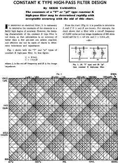
Fig. 1 - (A) "T" type and (B) "pi" type constant K high-pass filter.

By Seizo Yamasita

The constants of "T" or "pi" type constant K high-pass filter may be determined rapidly with acceptable accuracy with the aid of this chart.

In designing an electrical filter, it is customary to determine the constants of the elements to a fairly high degree of accuracy. However, the damping characteristic of the constant K type filter is not sharp, so that calculations to an accuracy of better than a few per-cent are seldom required, and effective use can be made of charts to determine inductance and capacitance.

Fig. 1 shows both the "T" and "pi" types of constant K high-pass filter. In this figure:

L = R/(4πf0)

C = 1/(4πf0R)

where f0 is the cut-off frequency and R is the image impedance.

From the chart (Fig. 2) it is possible to determine L and C if f0 and R are known. For example, the chart shows that a filter with a cut-off frequency of 10,000 cycles and an image impedance of 600 ohms would call for L = 4.8 mH. and C = 0.014 μfd.


Posted February 24, 2021

Crane Aerospace Electronics Microwave Solutions: Space Qualified Passive Products
everythingRF RF & Microwave Parts Database (h1)

RF Electronics Shapes, Stencils for Office, Visio by RF Cafe

PCB Directory (Manufacturers)