Constant-Resistance Network Inductor Design |
||
In this Radio & Television News magazine article, author Jack Gallagher derives a formula for the number of turns of wire to wind on a form of given dimensions for a parallel constant-resistance network. He argues that although commonly used formulas like that of Wheeler provide the number of turns needed to achieve a desired value of inductance, it does not predict the size of cross-sectional shape of a coil form that results in an optimal configuration. His work applies to audio frequency divider networks like those used for speakers to steer specific frequency ranges to a woofer, midrange, and tweeter trio; hence the need for "constant resistance" (e.g., for standard 8 Ω or 16 Ω speakers). By the way, in case you are not familiar with the annotation in older electronics articles, "mhy" is microhenries, and "s.c.c." is silver-covered copper (I'll bet almost nobody knows that!). Constant-Resistance Network Inductor Design
A useful formula for winding your own constant resistance inductances for dividing networks. It is unfortunate that articles which have been written concerning dividing networks have failed to give the reader an idea of how to wind inductances for these networks. The reader is usually given information about the types of circuits, the values of components used therein, and the fact that the inductance should be wound with heavy wire on non-magnetic forms, but usually no information is given about the size of form needed, the size of wire, and the number of turns of wire required for a given value of inductance.
Fig. 1 - Cross-section of coil. For maximum inductance c equals b; and c should be 0.66 of radius a. See text for explanation.
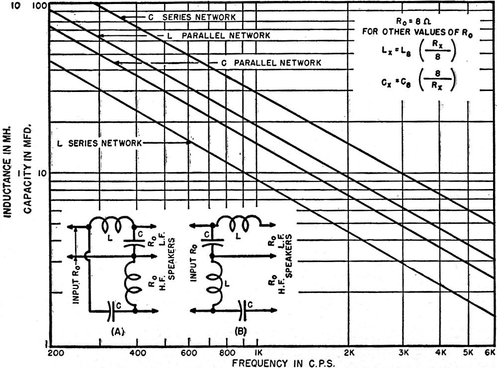
Fig. 2 - Inductance and capacitance of parallel (A) and series (B) circuits. Graphs shown are for R0 equal to 8 ohms. L-C equations for other values of R0 are included. Various circuits for dividing networks were described in the article "Dividing Networks" which appeared in the December issue of Radio & Television News, therefore it is the purpose of this article to present suitable information which can be used to determine the approximate number of turns required for a given value of inductance. Unfortunately, there has been no exact, simple formula derived whereby it is possible to calculate the number of turns to wind on a form of given dimensions to obtain a desired inductance. However, there are several formulas available which are sufficiently accurate for practical purposes and these can be employed, providing they are used with discretion. Wheeler's simple approximate formula for a multiple-layer inductance of the type shown in Fig. 1 is:
where dimensions are in inches. In order to obtain the maximum inductance and the most economical construction, the cross-section of the winding should be a square and the side of the cross-section should be 0.66 times the mean coil radius, "a" in Fig. 1. Then L reduces to: L = 0.043(a) (N)2 microhenrys In the parallel constant-resistance type of dividing network, as shown in Fig. 2A, the value of the inductance L is given by the formula:
Equating the two values of L above and noting that the mean coil radius "a" is equal to one-half of the inner diameter of the coil plus the depth of the winding "c", then simplifying, the formula for the number of turns of wire to wind on a form of given dimensions for a parallel constant-resistance network becomes
where D is the inner diameter of the coil in inches. Since no dimensions other than the inner diameter of the coil exist in the equation above, it may seem to be incomplete. It can be shown that the inner diameter of the coil is approximately twice the winding depth. To obtain the number of turns to wind on a form for the series constant-resistance type of network multiply the value of N for the parallel circuit by 0.707. As an example consider R0 as 8 ohms, the desired crossover frequency as 600 cycles, and the form as 1 1/2 inches in diameter. Substituting in the formula and solving for N we get 250 turns. The diameter of the form is 1 1/2 inches, therefore the depth and width of the winding space must be approximately equal to one-half the inner diameter (1 1/2 inches). Since the cross-section of the winding has been assumed to be square, the available winding area is 0.75 x 0.75 = 0.563 sq. in. Dividing 250 turns by 0.563 sq. in. will equal the number of turns per sq. in., or 444 in this case. A good copper wire table will give the number of turns per sq. in. for various sizes of wire. Number 18 enamel s.c.c. will wind approximately 454 turns per sq. in., therefore using this size of wire will allow a small margin in winding space. Suppose the series circuit was used instead of the parallel circuit, then the number of turns would be 250 x 0.707 = 176. This value divided by the winding area (0.563 sq. in.) equals 313 turns per sq. in., in which case number 16 s.c.c. should be used. The value of inductance obtained by this method will not be the exact value required by the network, but it will be approximately correct and satisfactory for practical purposes. For convenience, values of inductance and capacity can be read directly from the chart in Fig. 2. If the crossover frequency is 600 cycles and R0 is 8 ohms, then values of C and L can be obtained simply by following the 600 cycle line upward until the appropriate C and L lines are intersected. Thus, if the circuit is the parallel type the 600 cycle line intersects C for the parallel network at 24 μfd., and the inductance L required is 3 mhy. For other values of R0 the procedure is the same except that the values of C and L obtained are substituted in the formulas shown on the chart. References Terman, F. E.; "Radio Engineer's Handbook", McGraw-Hill Book Company, New York Read, Oliver; "The Recording and Reproduction of Sound", Howard W. Sam's & Co., Inc., Indianapolis
Posted March 27, 2020 |
||
 By Jack D. Gallagher, W5HZB
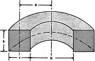
 microhenrys
  microhenrys
  ,
,