|
September 1932 Radio News
 [Table
of Contents] [Table
of Contents]
Wax nostalgic about and learn from the history of early
electronics. See articles from
Radio & Television News, published 1919-1959. All copyrights hereby
acknowledged.
|
Magnetrons and klystrons are
fairly ubiquitous in society these days for use in heating, radar, industrial processes,
cooking, and even lighting. They were probably the first useful means of producing
high power microwave signals. The concept was first brought to fruition in the early
1920s as a laboratory curiosity and rapidly developed into a practical type of device
with many applications and spin-off products like the klystron, the traveling wave
tube, and the cross-field amplifier. This article from a 1932 edition of Radio
News magazine reports on the state of the art a decade after the magnetron's
inception.
How to Construct a 56 Megacycle Magnetron Transmitter
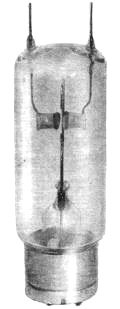
The Magnetron
Figure 1 - The tube which with its field coil offers new fields
of experimentation on the ultra-short waves.
Here it is, something new in radio! A new oscillator principle for the ultra-short
waves employing the gridless double plate tube in a manner comparable in many respects
to the Gill-Morill method. This article, a feature of the Radio News series on opening
up the ultra-short wave field, will be invaluable to the technician and earnest
experimental amateur
By James Millen

The High C Tuner
Figure 10 - This is the tuned circuit for resonating the new
magnetron oscillator tube as explained in the text.
The American amateur was the first to make practical use of the 200-meter band
and the first to develop the utility of still shorter and vastly more important
communication channels. A new field of research, the ultra-short waves, now challenges
his ingenuity, and we are sincere in our belief that here again the "ham" will make
a genuine contribution to ultra-high-frequency technique. The magnetron, in particular,
offers fertile possibilities, and its application to commercial enterprise may be,
to our way of thinking, materially accelerated by its exploitation and development
in the amateur ranks. This article finds dual justification in the effort to stimulate
such experimentation, and in presenting a practical 56-megacycle magnetron transmitter.
As we pointed out in the original article of this series, there exist a variety
of methods whereby ultra-short-wave energy can be set in motion. However, the necessity
for efficiency (reasonably high-power output for practical input powers) and stability
places a definite limitation on the systems serviceable for useful communication.
The magnetron, today, offers the most economical method for generating quasi-optical
power. As it is an electronic device, its functioning is perhaps best understood
by indicating its similarity to more conventional systems. It is not particularly
difficult to design the usual sort of tube oscillators for wavelengths between 5
and 10 meters, and by the utilization of their harmonics to extend this range to
a still lower minimum. However, as might be imagined, the stability of such systems
leaves much to be desired, and the power output is generally inadequate. Also, as
may be readily understood, maximum frequency limitations are necessarily imposed
by considerations of the capacity and inductance by which resonance is determined.
An additional complication, the fact that as the frequency is still further raised
the period approaches the times required for the electrons to complete their inter-electrode
cycle, imposes further limitations - at the same time offering a solution to the
problem. It was found that, under proper conditions, oscillations could be sustained
the frequency of which was dependent on the geometry of the tube or on the potentials
applied to the elements rather than upon the LC characteristics of the circuit.
Such systems have been described categorically as Barkhausen-Kurz circuits in deference
to their two most-prominent investigators. It is logical and true that such arrangements
are capable of delivering higher powers, at very short wavelengths, than those with
which we have become familiar on the conventional short waves. It was also discovered
that the power output could be increased by resonating the circuit to the natural
electronic frequency, and such transmitters have come to be known as Gill-Morill
circuits and are comparable in many respects with the magnetron system.

Set-up of the New Transmitter for 1 1/2 Meters
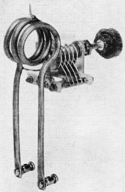
Figure 2 - This illustration shows the essentials of the magnetron oscillator
system. The field coil, rear center, has been removed from around the tube for clarity.
The particular arrangement shown is for a frequency range corresponding to approximately
1 1/2 meters. The plate supply circuit is not shown.
The magnetron is not a new tube. It has been with us for well over a decade,
and was originally designed as a tube in which electron control was effected by
magnetic influence rather than electrostatically. In other words, the grid of the
tube was a magnetic coil, and, peculiarly enough, the magnetron was first used as
a radio-frequency amplifier and oscillator in the neighborhood of 8000 meters!
The magnetron used in ultra-short-wave work varies from its prototype in several
essentials. The magnetic coil no longer functions as a grid (in the control sense),
but its effect is similar to that of a "bias." By increasing the magnetization current,
the space current can be cut off - corresponding to an increase in negative bias
in a conventional triode circuit. At optimum magnetic bias, the space current is
reduced while space charges build up within the tube. Connected with a suitable
circuit, a negative-resistance characteristic permits these charges to dissipate
and re-accumulate, producing a cycle the time constant of which is partly determined
by the spacing of the elements, the intensity of the magnetic field and the potentials
applied. Subsequent experiments have shown that, as in the Gill-Morill circuits,
the efficiency of the magnetron is greatly increased when the circuit resonance
approaches the natural electronic period.

The Magnetron Circuit
Figure 3 - The data supplied in this
article was obtained from a transmitter using this simple circuit. The top diagram
shows field coil hook-up.
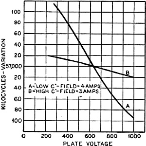
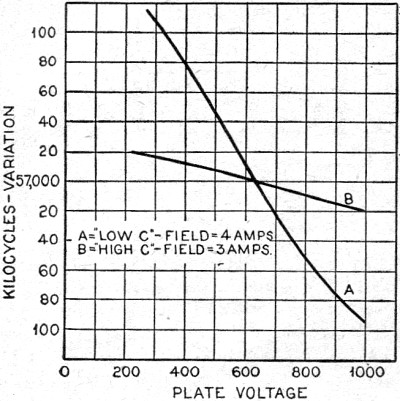
Frequency Variation
Figure 4 - Curves showing increased stability by using high C
circuit
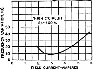
Choosing Proper Current
Figure 5 - Showing relation of field-current ripple and
frequency variation with the high C circuit

Obtaining Minimum Variation
Figure 6 - This is a field current, plate-voltage curve for getting
the least frequency variation

Modulation Data
Figure 7 - Linear relation of plate voltage-plate current adapts
the magnetron readily to modulation.
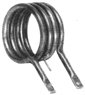
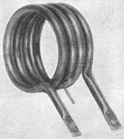
Low C Coil
Figure 9 - This is the tapped four turn low C coil used in the
original experiments.
The magnetron used in the experiments and transmitter to be described is the
GE-239, and is shown in Figure 1. The anode is split into two semi-cylindrical sections
mounted coaxially with the heavy tungsten filament. It is an air-cooled tube, used
principally as an oscillator. The lowest operable wavelength is 0.75 meters, and
at 1 meter, with a plate potential of 1500 volts, has a plate impedance of 5000
ohms. The maximum operating anode potentials are 1500 volts d.c. and 2000 volts
r.m.s. a.c. The maximum d.c. anode current is .075 ampere, and the maximum plate
dissipation 60 watts. The inter-electrode capacities are anode-to-anode (filament
grounded) .5 mmfd.; anode-to-filament (other anode grounded) .7 mmfd. The tungsten
filament draws 5 amperes at 5 volts.
The mechanical characteristics of the tube are indicated in the photographs.
The anodes are connected from the top, and the base plugs into a standard 50-watt
socket. The overall length is 10 inches; diameter 2 1/4 inches.
The output of this tube, in both power and stability (when properly operated)
is definitely superior to other arrangements, its output at .75 meter being vastly
better than that available with the B-K G-M circuits.
Figure 2 shows the experimental layout from which the various data accompanying
this article were secured. The circuit, as may be observed from Figure 3, is simplicity
itself.
It consists of the tube between the anodes of which is connected the center-tapped
coil. (As will be described, this coil was changed in the course of the experiments,
and an exterior capacity shunted across it. The simple inductor is shown in Figure
9 and the coil plus the tuning condenser, are shown in Figure 10.) The field coil
has been removed from its place around the magnetron for the sake of clarity.
The oscillating frequency is largely determined by the inductance and the capacity
of the circuit. For the highest frequency (400 megacycles), the inductance of the
anode leads and the capacity between them is sufficient. In this case the external
anode leads are short-circuited with a copper bar or ribbon) about one inch from
the glass, and the high voltage is connected to a tap at the center of the bar.
The Field Coil
The field coil is wound with 70 pounds of number 14 enameled wire, on a form
having an inside diameter of 5 inches. The length of winding is 5 inches, 74 turns
to the layer, with a total number of 2665 turns. Each layer is separated with paper
insulation .015-inch thick. The coil is excited with a potential of 100 volts through
a suitable resistor, providing a maximum current of 5.8 amperes and a maximum continuous
field strength of 830 gauss with a dissipation of 580 watts. The outside diameter
of the coil is 11 inches. The variable series resistor should be capable of carrying
the maximum excitation current and should have a resistance of at least 17 ohms.
The effect of the magnetic field on the operating characteristics of the magnetron
is, as we have already suggested, somewhat similar to that of a bias of the grid
of a triode oscillator. At low values of field, below 20 amperes, corresponding
to a small bias, the plates heat excessively; the plate current is high and the
efficiency is low. As the field is strengthened, the circuit becomes more stable,
operating with greatly improved efficiency and output. The current in this region
varies from 3 to 5 amperes. Plate-current "cut-off" can be obtained with an excitation
current of about 7 amperes.
In general, the requirements of the oscillatory circuit, in respect to efficiency,
stability, etc., are similar to those of the dynatron oscillator, although, of course,
the frequency range is much greater.
As the filament is tungsten, it is possible to operate it over a wide range of
voltages without encountering the trouble experienced with thoriated filaments.
It was found, however, that for best stability the filament should be operated near
its rated voltage - though a 10 or 15 percent. variation has a relatively small
effect.
The first tests, while altogether satisfactory in respect to output, left a great
deal to be desired from the standpoint of stability. Curve A, of Figure 4, illustrates
the manner in which frequency varied as the plate voltage was changed. In this original
experiment the tuned circuit consisted of 4 turns of 1/4-inch copper tubing, 2 inches
in diameter, mounted directly on the anode leads, the tuning capacity being the
inter-electrode capacity of the tube (about .5 mmfd.) and the distributed capacity
of the coil and leads.
The frequency was approximately 56 mc. The circuit and operating conditions under
which this test was made probably represented the most unfavorable, with respect
to frequency stability, that would be encountered in practice.
The total change in frequency, i.e., about 200 kc., seems rather appalling to
one familiar with the operation of low-frequency apparatus. As a matter of fact
it is not much worse than that encountered in a self-excited push-pull oscillator
operating on the same ultra-high frequency. Such as oscillator, however, cannot
be considered satisfactory. An investigation (with the idea of improving stability)
was therefore begun, and while it is not fully completed, it represents definite
steps in the right direction.
Stabilizing the Circuits
Each portion of the magnetron circuit has a relationship to frequency stability.
Variations in the magnetic field were very bothersome, so it was deemed advisable
first to investigate this. It was discovered that when a certain magnetic field
strength was employed, variations in the field current had a minimum effect on frequency
change. The optimum field current, from this point of view, was about 4 amperes.
This is important since the field-supply filtering is something of a problem, due
to the high current required. In these tests a motor-generator furnished the field
power and when the correct adjustment was attained, a monitoring test disclosed
the fact that such disturbances as commutator ripple and minor line-voltage variations
were no longer of major importance. The magnetron was not operating quite at its
maximum efficiency at this field setting, but the drop in efficiency was small enough
to be considered important in the light of the improved stability obtained.
The frequency variation, with change in plate voltage, was still the same, however,
so the "low C" circuit was abandoned in the hope that a certain amount of tuning
capacity would be beneficial. The magnetron operates most efficiently into an oscillatory
circuit of high impedance, making a "high C" circuit theoretically undesirable.
Nevertheless a tuned circuit was constructed employing a coil of 3 turns of 1/4-inch
copper tubing 1 1/2 inches in diameter, tuned with a condenser of about 20 mmfd.
capacity. Since the inter-electrode capacity of the tube is only about .5 mmfd.,
this additional capacity effected a considerable improvement in stability, without
serious loss in efficiency.
The operation of the circuit, as a whole, was quite different from the original
tests. Changes in field current, plate and filament voltages caused only a relatively
small variation in frequency. The curves in Figure 4 show the contrast between the
"low" and "high C" circuits.
A definite value of field current which minimized the effects of commutator ripple,
etc., was found as before, but was considerably lower in value, being approximately
3 amperes instead of 4 amperes (Figure 5). It is interesting to note that the optimum
operating value of field current, with regard to frequency instability caused by
field variation, is approximately the same at all plate voltages, as is shown in
Figure 6. As before, better output was obtained with the field current reduced slightly
from that value giving most stable operation. The choice of field current will therefore
depend somewhat on operating conditions. If a well-filtered supply is available,
efficiency and output are the deciding factors. Where the field supply is subject
to variation, stability is the predominant consideration .
The value of R is not critical as far as efficiency or frequency vs. plate-voltage
variations are concerned. However, it was found that by the correct adjustment of
R, frequency variations due to field strength changes could be still further reduced
materially. The actual value varies between 100 and 400 ohms and depends on the
plate voltage - higher resistance being required for higher potentials. Some energy
is necessarily dissipated in this resistor, but this loss is relatively unimportant
in view of the main goal of a stable circuit. Also, some compensation of this loss
is achieved through an improved anode circuit efficiency.
A d.c. Filament Source Preferred
After a fair degree of stability had been attained, as indicated in curve B,
Figure 4, another source of trouble became evident. This was vibration of the filament
structure of the tube, due to the filament current, which was alternating current,
reacting in a "motor" effect with the strong d.c. field. When the filament was light
by d.c., this trouble was eliminated.
Modulating the Circuit
Referring to the curves in Figure 7, it is immediately seen that the relation
between the plate current and plate voltage is essentially linear, and the circuit,
therefore, lends itself admirably to modulation. From the slope of the curve, the
effective plate impedance is found to be about 9000 ohms, which, while somewhat
higher than that commonly encountered in the usual transmitting tubes of similar
power, should present no serious difficulty from the standpoint of obtaining a satisfactory
impedance relationship in the modulator output circuit.
Photograph, Figure 8, shows the complete set-up of the magnetron, with its attendant
apparatus, including modulation and speech equipment. The modulator consists of
two type -50 tubes in push-pull, connected through a suitable transformer to the
oscillator plate circuit. Since the magnetron was operating with an input of about
35 watts at 650 volts, a fair percentage of modulation was obtained with the two
-50's operating at the same plate potential. In any case the modulation should not
exceed 70% if reasonably good fidelity is desired. The speech equipment and amplifier
circuits are quite conventional.
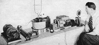
Complete 5 Meter Amateur Phone Transmitter
Figure 8 - Robert
McCoy of the Jackson Research Laboratories shown operating the station. The high
C tuned circuit may be seen just above the field coil which is in correct position
surrounding the coil. Speech amplifier equipment is at the right energized by a
storage battery and B batteries. The motor generator supplies the field coil energy.
The radiating system was a simple vertical, half-wave, copper-rod antenna approximately
8 feet long, and fed by means of a balanced transmission line.
Transmitting Tests
Field tests were made up to distances of about 5 miles, the signal being checked
in comparison with that of a conventional modulated oscillator. Two types of receivers
were used, one being a super-regenerator, and the other the latest type of ultra-high-frequency
superheterodyne described in Radio News for August. It was, of course, impossible
to check the effects of frequency modulation of the super-regenerator since the
receiver itself is subject to a degree of frequency modulation from the suppressor
frequency that is comparable with that of the worst transmitter. Due to this fact,
only slight differences between the transmitters were apparent on the first receiver
(the signal from the magnetron was appreciably sharper, but the tone quality was
not noticeably better.)
On the other hand, when using the super-heterodyne, the magnetron was found to
give a clear-cut signal of good quality, in contrast to a decidedly broad and wobbly
signal of low intelligibility from the modulated oscillator.
The tests definitely checked the various circuit requirements that laboratory
experiments had indicated to be desirable. Of the two transmitters, each employing
similar modulating equipment, the magnetron gave a much stronger signal due, of
course, to the higher degree of efficiency. Increased power at these frequencies
does not result in a corresponding extension of range, since the behavior of the
signal tends to comply with optical laws. However, the stronger signal was found
to be much more effective in location subject to local interference.
The possibility of modulating the r.f. output of the circuit by supplying the
modulating power to the field coil will doubtless occur to many experimenters. However,
aside from the difficulty of controlling the high excitation current with any depth
of audio-frequency variation, field circuit modulation might be undesirable due
to the excessive change in radio-frequency with field current change. Also, the
r.f. output does not vary uniformly with the field, except over rather small limits
and when using a somewhat restricted range of plate voltages.
Higher Frequency Possibilities
The tests described above were confined to the neighborhood of 56 megacycles.
A vast amount of experimentation still remains before the possibilities of the magnetron
are fully realized on frequencies above 300 megacycles (below 1 meter). Work in
this region, which is not being used at present for any practical purpose, affords
a highly interesting and unusually fertile field for the experimenter, and the magnetron,
at the present time, is the tube best suited for this phase of exploration.
* The National Co.
Posted November 26, 2021
(updated from original post on 10/21/2014)
|