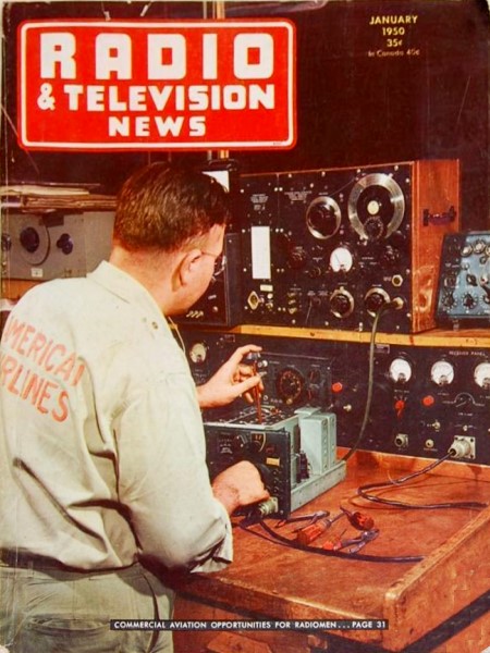
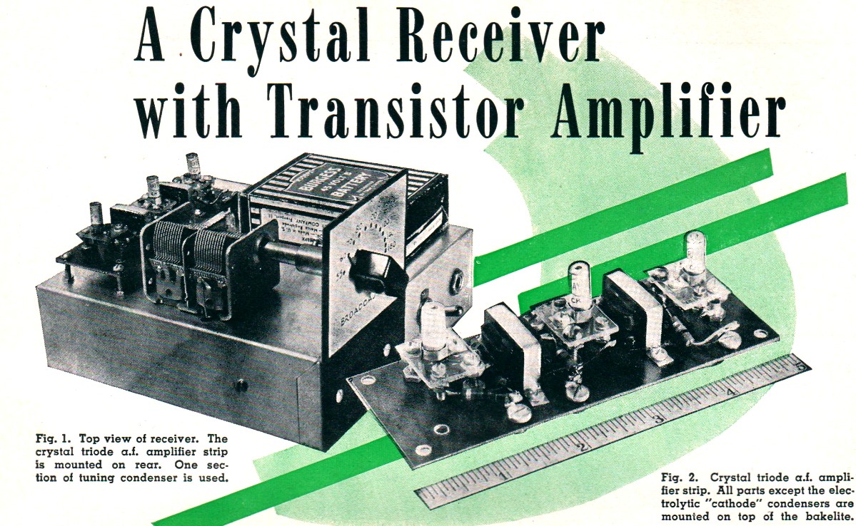
A Crystal Receiver with Transistor Amplifier |
||
Considering that not much more than a year before this article was written in 1950 for Radio & Television News magazine that the transistor had been invented, it is impressive that already Raytheon was producing a commercially available CK703 "crystal triode." That nomenclature was a natural extension of the preceding crystal diode already being widely adapted in circuit design. If you have wondered how the transistor schematic symbol came to be as it is, you will learn why here where the emitter and collector symbols actually both have arrows on the ends that contact the base, indicating the "point contact" physical arrangement of the semiconductor junctions. Shortly thereafter the arrow on the collector port was eliminated, primarily, I suppose to avoid confusion when the E, B, and C labels are not present. A Crystal Receiver with Transistor Amplifier
Fig. 1 - Top view of receiver. The crystal triode a.f. amplifier strip is mounted on rear. One section of tuning condenser is used. Fig. 2 - Crystal triode a.f. amplifier strip. All parts except the electrolytic "cathode" condensers are mounted on top of the Bakelite. The recent appearance of the transistor on the commercial market opens new fields to the radio experimenter. One of its uses is discussed here. The introduction of Raytheon's new CK-703 crystal triode opens up a new field of interest for the radio experimenter. Recommended for use at frequencies up to the video range, this commercial transistor can be used as a medium mu a.f. or r.f. amplifier, oscillator, or control "tube." Simple, small-sized, and lightweight electronic equipment may be built around crystal triodes. Enterprising radio men undoubtedly will find a host of applications for this device. This article describes a simple crystal diode broadcast receiver with a crystal triode audio amplifier. Although this set will not operate a loudspeaker, it will give a walloping good signal in high-impedance headphones, provided it is connected to a good outside antenna and ground. A great deal of satisfaction may be derived from its operation, and some experience with crystal triodes gained as well. Before describing the receiver, however, we will explain briefly the characteristics and construction of the crystal triode. Features of Transistor
Fig. 3 - Under chassis view of the receiver showing components and simple wiring.
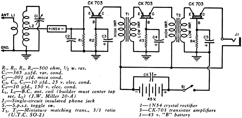
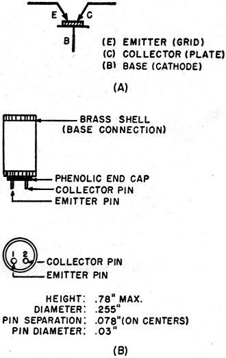
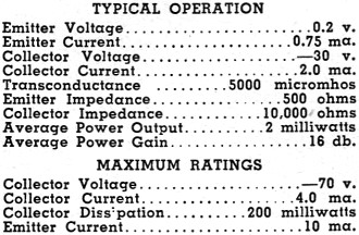
Fig. 4 - Complete circuit diagram and parts list for the crystal-transistor receiver. The transistor is a germanium crystal device. It differs from the familiar crystal diode, of which the 1N34 is a well known example, chiefly in that the transistor has two cat whiskers instead of one. One whisker, called the emitter, acts in a manner comparable to the grid of a triode vacuum tube. The point of the second whisker, called the collector, touches the surface of the germanium crystal extremely close to the place of contact of the first whisker and acts like the plate of a triode tube. The crystal itself (called the base in crystal triode terminology) is comparable to the cathode of a tube. Unlike a tube, however, the emitter (grid) of the crystal triode is biased with a low positive voltage, while the collector (plate) receives a high negative voltage. Another important difference is that the crystal triode has a low-impedance input and a high-impedance output. The recommended circuit symbol for the transistor is shown in Fig. 5A. The CK-703 (See Figs. 5B and 7) is a small-sized unit, being only 0.78 inch (maximum) long and 0.255 inch in diameter. The housing of the CK-703 is a cylindrical brass shell to which the crystal is connected internally. This shell serves as the base (cathode) terminal. The emitter and collector whiskers are connected to two nickel contact pins which extend through an insulating disc-plug in one end of the brass shell. Fig. 5B identifies these pins in bottom view. The CK-703 has an input (emitter) impedance of 500 ohms and output (collector) impedance of 10,000 ohms. It is rated at 2 milliwatts average power output with an average power gain of 16 db. The power rating is on the basis of a 50-microwatt signal applied to the emitter. Table 1 gives the important electrical characteristics of the CK-703. From the impedance ratings, it is evident that a conventional amplifier circuit employing crystal triodes must provide for an impedance step-down between stages. This means that interstage transformers must have a step-down turns ratio. Receiver Circuit Fig. 4 is the complete schematic for the receiver. This circuit is entirely conventional except for the employment of a 3-stage crystal triode audio amplifier. The input coupler, L1-L2 is a standard broadcast antenna coil of the type used in midget receivers (J. W. Miller 20-A). This coil has been center tapped in order to match the impedance of the crystal detector more effectively and to improve selectivity. The center tap must be provided by the builder, since this coil normally is not supplied with one. Tuning is accomplished by means of a midget 365 μμfd. variable condenser, C1. The detector diode is the new Sylvania 1N54 high-efficiency unit. The cathode of this diode is connected directly to the high end of a 500 ohm load resistor, R1, and to the emitter terminal of the first CK-703 socket.
Fig. 5 - (A) Circuit symbols for the transistor. (B) Details of CK-703 crystal triode.
Table 1. Electrical characteristics of CK-703.
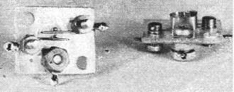
Fig. 6 - Home-made wafer-type CK-703 sockets. Bottom view shows transistor plugged into socket with the two base pins in contact with the wire springs. Brass shell for gripping the CK-703 case is shown at right.
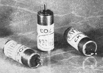
Fig. 7 - Three new CK-703 crystal triodes. The contact pins are the collector (plate) and emitter (grid) terminals. Brass shell is connected to the crystal and is the base (cathode) terminal. Triode is 0.78" by 0.255". In order to dispense with emitter batteries in the amplifier, the author has employed base or "cathode" resistors, R2 R3 and R4, in each stage. Collector current flowing through each of these resistors develops a voltage drop which is applied as a small positive potential to the emitter terminals. The 500 ohm value is correct for R2 R3, and R4. Reducing this resistance decreases power output and increases distortion. While there has been some criticism regarding this method of operation, it has given satisfactory operation in practice. The interstage transformers, T1 and T2 employed by the author are U.T.C. sub-ouncers Type SO-2. These transformers are connected backward. That is, the normal secondary (high impedance) is connected to the collector output of one crystal triode, while the primary (low impedance) is connected to the emitter input of the following crystal triode. While these transformers were not designed specifically for this application, they have approximately the proper turns ratio for the required impedance transformation and are very small in size. To improve fidelity, an individual builder may prefer to shunt-connect the transformers to keep d.c. out of their windings. The headphones are connected in series, through the output jack, with the collector of the last crystal triode and the negative battery terminal. Operation of a pair of 2000 ohm headphones has been satisfactory in this circuit. In the event that crystal headphones are used it will be necessary to use a choke and condenser coupling arrangement to keep the d.c. out of the headphones. Construction A single 45 volt battery is employed for power and is bypassed by a 10 μfd., 150 volt electrolytic condenser, C6. There is sufficient voltage drop across the high-impedance windings of the two transformers to reduce the collector-to-base d.c. voltage in each amplifier stage to about 37 volts . It is absolutely imperative that proper polarities of the crystal diode and of the three crystal triodes be observed. For this reason, the cathode terminal of the diode has been labeled in Fig. 4, and so have the emitter (E), collector (C), and base (B) terminals of each crystal triode. The builder must be careful to ground the positive terminals of electrolytic condensers C3, C4, and C5 and also to connect the positive battery terminal to ground. It will be easy to make a mistake in these connections, since radio technicians are well-schooled in the opposite procedure of connecting "B-minus" and the negative terminals of cathode bypass condensers to ground. The crystal triodes definitely will be burned out if the battery polarity is reversed. At this writing, no sockets have been manufactured for the CK-703. For this reason, the author made his own. Fig. 8 gives constructional details of the homemade socket, and Fig. 6 shows two completed sockets. Undoubtedly, the sockets could have been made smaller in size. The reader who is mechanically proficient may prefer to follow an entirely different design. The basic requirement in the transistor socket is that good contact be made separately to the outer metal shell of the CK-703 and to each of the base pins. Whatever type of contact is used, it must grip the shell and pins firmly but without bending, twisting, or denting. Soldering to the CK-703 is not advised. The author's socket (See Figs. 6 and 8) consists of a ring-shaped base shell for clamping the CK-703 shell, and two short lengths of spring wire for pressure contact against the side of each base pin. The wafer is a rectangular piece of thin Lucite, but can be made of Bakelite or other phenolic. The CK-703 is inserted into the tight-fitting base shell, and its pins pass through small-diameter clearance holes in the wafer to be contacted by the straight wire springs mounted underneath. Small soldering lugs are provided for circuit connections to the three contact members of the socket. Since the contact pins protrude just below the center line of the CK-703 base (See Fig. 5B), the unit can be plugged into the socket only in the correct position. Thus, all danger is removed of inserting emitter or collector pin into the wrong hole. The entire audio amplifier is built on a strip of 1/16-inch-thick Bakelite, 4 7/8" long and 1 3/4," wide. Fig. 2 is a view of this amplifier strip. All components are mounted on the strip, except condensers C3, C4, and C5 which are mounted directly under the main chassis (See Fig. 3), and electrolytic condenser C6 which is "hung" between the battery terminals. The small coupling transformers are held to the strip by means of bands bent from 3/16"-wide brass. (These mounting bands must not be used if the transformers are mounted directly in contact with a metal chassis, since they might form eddy current loops). The amplifier strip is supported on the chassis (See Fig. 1) by means of four 1-inch 6-32 screws. The entire set, as shown in Fig. 1, is built on a 7"x7"x2" metal chassis. The tuning dial plate is home-made. The headphone jack, which must be insulated from the chassis, is mounted along the front lip of the chassis, as is the battery "On-Off" switch. The author employed a 2-section tuning condenser (with only one section in use), as shown in Fig. 1, simply because a single-section unit was not immediately available. The antenna coil, L1-L2, is mounted under the chassis directly below the tuning condenser. This coil is provided with a slip-over primary (L1) which may be slid off temporarily while a center tap is soldered to the secondary coil (L2). Center tapping the coil is a delicate operation, since the coil is wound with rather fine wire. But it can be accomplished easily, provided a reasonable amount of care is used. Locate the center turn and, using a sharp razor blade, carefully scrape about 1/4 inch of the enamel off the wire. Avoid scraping the adjacent turns. Solder a length of No. 32 insulated wire to this scraped portion, replace the primary, and run the tap lead directly to the 1N54 crystal diode. For simple mounting, the 1N54 pigtails are soldered to a 2-lug insulated terminal strip mounted near the coil. The r.f. bypass condenser, C2, is mounted near the 1N54. Load resistor R1 is mounted on the audio amplifier strip near the first CK-703.
Fig. 8 - Construction details of transistor socket. The terminal markings (E, C, and B) indicated on both of the lower drawings refer to the symbols given in Fig. 5A. Hookup wire leads from the amplifier strip and battery pass through clearance holes in the chassis to reach under-chassis contact points. A stiff, bare lead extends from the tuning condenser stator lug through a large chassis clearance hole to the coil, L2 below the chassis.
Testing and Alignment Do not connect the battery until all connections in the circuit have been checked and found to be correct. After verification, connect the battery, plug in the high-impedance headphones, and throw the "On-Off" switch to "On." A gentle rushing sound should be heard, due to the inherent noise level of the crystal triodes, but there should be no oscillation nor singing. If there is oscillation, it will be necessary to re-run critical leads and possibly to orient the transformers to prevent the feedback. A modulated r.f. signal generator may then be connected to the antenna and ground leads of the receiver and the dial calibrated at fixed broadcast band points in the usual manner. Use the signal in the headphones to indicate resonant points, or connect a high-resistance a.c. voltmeter in parallel with the headphones for visual indication. If a manufactured broadcast dial is used, line-up first at the top of the band (1600 kc.) and bend the outside plates of the tuning condenser to make the other frequencies coincide with the dial graduations. The noise level of the crystal triodes is somewhat higher than with comparable triodes in the same circuit, but is not objectionable in this arrangement. In the absence of a signal, a soft steady hiss will be heard. Current drain of the amplifier is low and the battery consequently will give long service. However, the receiver should be switched off whenever it is not in use. This will prolong the life of the battery and of the crystal triodes as well. The set should not be left connected to the outside antenna during a thunderstorm unless an efficient lightning arrestor is attached. No data is available at this writing regarding transistor life. The crystal triode is not yet old enough to have undergone prolonged life tests. However, it seems reasonable to expect life comparable to that of germanium diodes which presently are guaranteed up to 5000 hours. The little receiver shown in this article is only an example of successful crystal triode application. The author does not intend to imply that this is the ultimate by any means. Certainly, a much smaller set could be built and a smaller battery of the hearing aid type could be employed. Higher power output can be obtained by using 4 transistors in push-pull parallel in the output stage. A crystal triode r.f. amplifier might be added. An individual experimenter may prefer to employ fixed emitter bias, possibly derived from a "lower than ground" point on a voltage divider across the battery. Many applications, other than receivers and audio amplifiers, will undoubtedly occur to the reader.
Posted March 29, 2022 |
||