|
June/July 1940 National Radio News
 [Table
of Contents] These articles are scanned and OCRed from old editions of the
National Radio News magazine. Here is a list of the
National Radio News articles I have already posted. All copyrights are hereby acknowledged. [Table
of Contents] These articles are scanned and OCRed from old editions of the
National Radio News magazine. Here is a list of the
National Radio News articles I have already posted. All copyrights are hereby acknowledged. |
The old pushbutton radio
tuners were an ingenuous bit of electromechanical wizardry. For those too young
to have experienced them, operation was simple - turn the radio tuning knob to your
broadcast station, pull out the lever/button, and then push it all the way back
in. Done. The next time you pushed that button, the mechanism would slew the dial
indicator to that position, taking the tuning elements (usually just a variable capacitor)
with it. For most modern electronic radios, you program the station button by pushing
and holding it for a few seconds until a beep is heard. My father never quite got
the hang of tuning the pushbutton radio in his old Rambler (vacuum tubes) or even
his 1978 Chevy pickup truck (transistorized, but with mechanical tuner). He was never
an early - or late for that matter - adopter of new technology, so it was not surprising.
I am surprised, though, at the number of times I have had to show a Millennial type
how to program his/her late model car radio.
My 1941 Crosley 03CB console radio has two banks of
tuner pushbuttons, in case you want to see some real-world examples.
Make Extra Profits Changing Push-Button Radios to New Frequencies
By J. A. Dowie, N. R. I. Chief Instructor
Some time within the next 12 months, approximately 90% of the broadcast stations
in this country are scheduled to change their frequencies to the new values set
forth in the Havana Treaty. This means that everyone of the approximately eight
million push-button-tuned radio receivers must be readjusted. It will be harvest
time for radio servicemen, so be prepared! Study carefully this timely article which
tells how you, as an N. R. I. student or graduate, can get your share of this profitable
business.
"How do you do, Madam. I am not the census taker, but there is a question I would
like to ask you. Does your radio receiver have push-button tuning? It does - well
that means some of the push-buttons will have to be reset when our local radio stations
change to new frequencies. Over eight million sets like yours will need this readjustment,
for stations all over the country will change frequencies at the same time. Servicemen
can't possibly take care of all these sets at one time, but by lining up the work
in advance and scheduling jobs carefully, I can promise to have your receiver readjusted
within twenty-four hours of the change-over time. By concentrating my work in this
one vicinity, I can go from one set to another with a minimum of time wasted in
travel and keep the cost of the work down to a very low figure.
"How much will it cost - well, it won't be more than $3 regardless of what make
of receiver you have, and may be a lot less. Let me take a look at your set and
I'll give you a definite figure. Here it is - and there's the push-button mechanism
on top of the chassis. It is one of the simpler types, so the charge for readjusting
it will be only $1.50. Is that all right? Fine - I'll make out a job ticket now,
and phone you when the change-over is being made, so we can set a mutually convenient
time for the work."
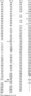
Fig. 1 - Table giving changes in channel assignments as
set forth in the Havana Treaty. A broadcast station now assigned to a channel in
Col. 1 will be changed to the channel on the same horizontal line in Col. 2. All
figures represent kilocycles.
Conversations like this will be heard all over the country this summer, as radio
servicemen prepare in advance for the biggest rush of work in the history of radio.
The forthcoming frequency reallocation comes as a result of the recent ratification
by Mexico of the Havana Treaty. This treaty was drafted in Havana, Cuba, two years
ago by representatives of Canada, Cuba, Mexico and the United States and is formally
known a the North American Broadcasting Agreement. The chief purpose of the treaty
is to reduce interference between stations, particularly the interference created
in this country by the high-powered Mexican border stations. Under the treaty, the
border stations such as 180,000-watt XERA and 50,000-watt XENT lose their present
high-power assignments on preempted channels.
The exact date at which the frequency shift will take place has not been set
by the Federal Communications Commission at the time of going to press with this
issue, but ample notice will undoubtedly be given the public in advance by radio
stations and newspapers. About 90% of the radio stations in the United States will
change frequency, so it is extremely unlikely that any present setting of four or
more push-buttons on a receiver will remain correct after the change-over.
The accompanying table indicates the general trend of the frequency changes.
In individual cases, changes not in accordance with the tabulated values may be
made to avoid interference on adjacent channels or for other reasons. Note that
present frequency assignments (Column 1 in. Figure 1) will remain the same after
the change-over for all channels between 550 kc. and 720 kc. inclusive. All other
stations will, in most cases,. have their frequencies increased. No stations will;
be dropped.
Naturally, if you are to get your share of this profitable business, you must
know how the various types of push-button systems work and must know how to set
them up.
Types of Automatic Tuning Systems
Although manufacturers have used many different schemes for providing automatic
tuning, we can divide these into three groups according to the operating principle
employed, as follows:
1. Mechanical Automatic Tuning Systems. By pressing a button or rotating
a telephone-type-dial, the listener himself provides the force required to rotate
the gang tuning condenser to the setting for a desired station. This is a purely
mechanical action, with no electrical switching whatsoever; tuning is essentially
instantaneous.
2. Electrical Automatic Tuning Systems. Pressing a button switches an
entirely new set of condensers, preadjusted to a particular station, into the tuning
circuit of the receiver in place of the gang tuning condenser. The action here is
entirely electrical, hence tuning is instantaneous.
3. Electro-Mechanical Automatic Tuning Systems. Pressing a button closes
the circuit to a small electric motor, which then rotates the gang tuning condenser
to a desired station. Electrical switching here causes a mechanical force to be
applied to the gang tuning condenser. A certain amount of time is required, once
a button is pressed, for the motor to complete the tuning process.
In all three systems, the initial adjustments which insure accurate automatic
tuning to desired stations have been made by the radio dealer at the time of the
installation. Printed tabs having the call letters of the desired stations are attached
to the push-buttons themselves or to the escutcheon surrounding the buttons, to
identify the station selected by each button.
Mechanical Automatic Tuning Systems
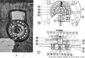
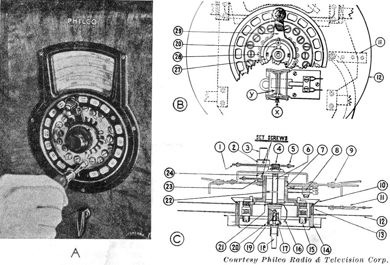
Courtesy Philco Radio & Television Corp.
Fig. 2 - Three views of an automatic tuning system used
on a number of Philco receivers which also have A.F.C. The numbered parts on these
diagrams are all identified in the Philco service bulletin on automatic tuning.

Fig. 3 - Operating principles of direct push types of mechanical
automatic tuning systems employing a cam with either a lever and roller or a plunger.
Pressure on the button in the direction indicated by the heavy arrow serves to rotate
the gang tuning condenser (geared to the cam shaft) to the correct setting for the
station assigned to that button.
Mechanical automatic tuning systems may be divided into two general groups according
to the manner in which they are operated by the listener:
1. Rotary or telephone-dial types, in which the listener himself provides the
rotary motion which turns the tuning mechanism to the correct setting for a desired
station. Automatic stops prevent him from moving beyond the correct setting.
2. Direct push types, in which the listener applies a direct push or force to
a button or lever. Either a gear, cam or lever arrangement is used to convert this
force into the rotary motion required to turn the tuning condenser to the correct
setting for a desired station.
Philco Automatic Tuning Dial. The general appearance of the Philco telephone
type automatic tuning dial with cover plate removed is shown in Fig. 2A. Constructional
details of this mechanism can be seen by studying the front-view diagram in Fig. 2B
and the cross-section view in Fig. 2C.
In setting up this Philco automatic dial tuning system, a station is first tuned
in the conventional manner, with the a.f.c. or magnetic tuning control in its "out"
position. The key (item 15) at the bottom of the dial is then adjusted by inserting
a screwdriver in its slot, pressing the key in slightly so it is free to rotate,
then turning the key until a click is heard. The receiver is now tuned for maximum
output by turning the key back and forth slightly. This procedure is repeated for
each other station selected.
Direct Push Types of Mechanical Automatic Tuning Systems.
A number of different mechanisms are being used to convert an ordinary direct
push on a button into rotation of a tuning condenser to the correct setting for
a desired station; let us look over a few of them.
In receivers employing mechanical automatic tuning units, there will be one complete
set of parts like those in Fig. 3, 4 or 5 for each station which is to be tuned
automatically. Pressure on the station-selecting button will cause the tuning condenser
shaft to rotate. The cams for the different stations are mounted side by side on
a cam shaft which is geared to the tuning condenser shaft, the cams being separated
by spacing washers and held in position by friction. A mechanical locking device
is provided for locking each earn rigidly in position once it is adjusted for a
station.
In some systems a straight plunger, with or without a roller, is used in place
of a lever arm.
In another system of the direct-push type, illustrated in Fig. 4A, the earn
is somewhat egg-shaped and the roller is replaced by a U-shaped or forked metal
piece. Pressing the button makes the forked plunger take the position shown in Fig. 4B,
holding the cam in a definite position.
A finger and rocker mechanism which provides mechanical tuning in still another
manner is illustrated in Figs. 5A and 5B, and a sketch of this unit is shown in
Fig. 5C. For each station there is a plunger (flat metal strip) sliding freely
through two slots in opposite sides of a metal frame. At one end of this plunger
is the push-button; clamped to one face of the plunger is a metal "finger" which
can be set at any desired angle to the plunger and held in position by a locking
screw and clamp arrangement (omitted from Figs. 5A and 5B to simplify the diagrams,
but shown in Fig. 5C). Pressing in a button makes the rocker rotate to the
same angle as the finger; on the rocker is a gear segment which meshes with a gear
on the tuning condenser shaft and thus provides the correct tuning condenser setting
for the station assigned to that button.
Electrical Automatic Tuning Systems
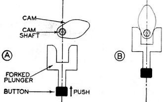
Fig. 4 - Egg-shaped cam and plunger mechanism used in the
mechanical automatic tuning systems of some Philco receivers.

Fig. 5 - The diagrams at A and B show one of the finger
and rocker units used in the mechanical automatic tuning systems of some Crosley
receivers (including the Crosley Safety-Tune auto radio), while the sketch at C
shows the complete tuning unit with a gear drive to a gang tuning condenser. Tightening
the screw on the plunger locks the finger rigidly in position. To set up a button
for a station, this screw is loosened so the finger can rotate, the button is pushed
all the way in, the station is tuned in manually, and the screw is tightened to
lock the finger at the correct angle. A spring returns the button to its normal
position when pressure is released, leaving the tuning condenser at the correct
setting for the desired station.
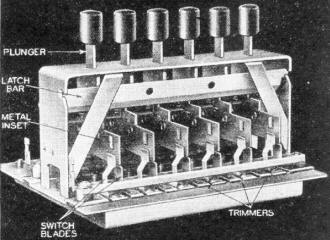
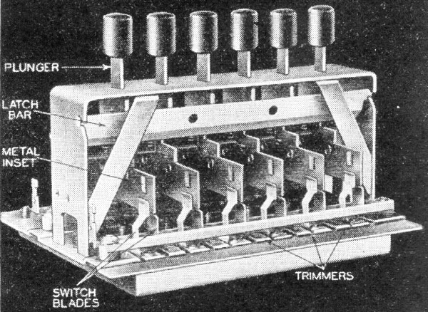
Fig. 6A - Sprague electrical automatic tuning unit with
built-in trimmer condensers. The switch blades in the foreground are normally held
apart by the strip of insulating material mounted on each plunger; when a button
is pressed, the metal inset moves down between the blades, shorting them and closing
the circuit to one set of trimmer condensers.
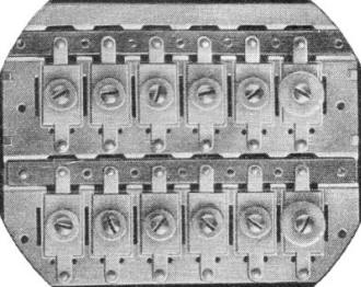
Courtesy Sprague Products Co.
Fig. 6B - Bottom view of the Sprague unit, showing the trimmer
condensers and their adjusting screws, Each push-button controls one upper and one
lower trimmer on this gang assembly. One terminal of each trimmer is grounded to
the frame of the unit, and this frame is in turn grounded to the chassis.
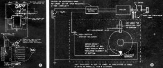
ig. 7 - RCA electro-mechanical automatic tuning system. Shaft
coupling units are designated as BB.
Instead of rotating the tuning condenser when a new station is desired, electric
automatic tuning actually removes the variable condensers in the tuned circuits
and replaces them with new condensers which were previously adjusted to the correct
values for that particular desired station.
Push-button switching mechanisms like that shown in Fig. 6A are used in
electrical automatic tuning systems. When one of the buttons on this unit is pressed
down, the button which formerly was down is released, removing that set of condensers,
and an entirely new set of condensers is switched in. The entire process of switching
is practically instantaneous. It is common practice to mount the set of preadjusted
condensers right on the switching mechanism. In Fig. 6B is a bottom view of
the unit in Fig. 6A; as you can see, there are two trimmer condensers, each
adjusted by a screw, for each of the buttons on the unit.
To secure better frequency stability, some manufacturers are using a push-button
switching system to substitute adjustable coils instead of trimmer condensers in
the oscillator tuned circuit. Special coils employing pulverized iron cores which
can be moved by means of an adjusting screw to change the inductance of the coil
are used for this purpose. A fixed condenser, usually of the temperature-compensating
type, provides the necessary capacity for the oscillator circuit. Because of the
higher cost of variable-permeability iron-core coils, they are usually used only
in the oscillator circuit. A slight change in trimmer condenser capacity will have
far more detuning effect in the oscillator tuned circuit than in a preselector tuned
circuit.
Initial Adjustments. It is neither advisable nor necessary to make each
adjustable part in an electrical automatic tuning system cover the entire 540 to
1,500-kc. broadcast band. A more economical and stable construction is secured by
limiting the tuning range of each adjustable coil or trimmer condenser to a definite
section of the broadcast band; for example, one set of adjustable parts may be designed
to tune from 540 to 900 kc., another set may coyer the range from 700 to 1,300 kc.,
and the third and final set might coyer the range from 1.000 to 1,500 kc. There
is enough overlapping between these three groups so that a station near the limit
of one group may also be tuned in by another group.
Instruct the customer beforehand to turn on the receiver at least half an hour
before you arrive, so the chassis will reach its stable operating temperature.
To reset a button for a station, tune in the station manually and note the nature
of its program at that time. Now push in the button assigned to that station. Locate
the oscillator trimmer condenser or variable inductance controlled by that button,
and adjust until the station is heard with maximum audio output. For best results
do not depend upon your ears, but use an output indicator or the tuning indicator
in the receiver (if available). With this done, locate the preselector trimmer condenser
which is controlled by this button and adjust for maximum output in the same manner;
you will note that this adjustment is quite broad, whereas the setting of the oscillator
trimmer was quite critical. Repeat this procedure for each other push-button.
Electro-Mechanical Automatic Tuning Systems
Electro-mechanical automatic tuning systems will generally include the following
sections:
1. A small electric motor which drives the gang tuning condenser through speed-reducing
gears and which can be reversed by means of a switch.
2. A switching mechanism which can be adjusted too stop the driving motor at
predetermined positions which correspond to the gang tuning condenser settings for
desired stations.
3. A group of push-button-controlled switches, each of which starts the motor
and connects into the motor circuit the proper switch mechanism for stopping the
motor at the correct point (these may be located at any reasonable distance away
from the receiver, making remote control tuning possible).
44. A means for silencing the audio system of the receiver during the interval
when the motor is driving the tuning condenser, in order to prevent annoying blasts
of sound as the receiver is tuned past strong undesired stations; a means for releasing
temporarily the a.f.c. system while the tuning motor is in motion or just after
it stops, in order to allow the desired station to "take hold" of the a.f.c. system.
RCA Electro-Mechanical Automatic Tuning System. A top view of this tuning
mechanism is shown in Fig. 7A, and the simplified diagram in Fig. 7B shows
how the system operates. The metal disc with an insulated segment and a slot on
opposite sides is one of eight discs which are mounted on a common shaft and held
in position by friction; beneath each disc is a spring contact. During manual tuning
the metal discs turn with the gang tuning condenser but the electric motor remains
motionless since the pin on its shaft is not engaged with the crank arm on the speed-reducing
gear.
To make the preliminary station-setting adjustment for this RCA mechanism, one
of the buttons is pressed, and after the motor has stopped, an adjusting key (provided
with the unit and kept in a special adjusting key receptacle when not in use) is
inserted in the adjusting hole corresponding to this button; this places the key
in the slot on the metal disc, exactly as shown in Fig. 7B. The a.f.c. system
is turned off by means of a switch on the receiver panel, and the receiver is now
tuned manually to the station desired for that button. Removal of the adjusting
key completes the adjustment for this station; the process is then repeated for
each other button. It is not necessary to lock the metal discs in position, since
there is sufficient friction to prevent them from slipping during normal receiver
operation.
Conclusions. In general, the telephone dial types of automatic tuning units will
be the most difficult to readjust. If your preliminary examination indicates that
trouble may be encountered, it will be wise to write in advance to the manufacturer
for instructions on setting up the tuner.
Posted May 6, 2022
(updated from original post on 10/28/2015)
|