Wax nostalgic about and learn from the history of early
electronics. See articles from Radio & Television News, published 1919-1959. All copyrights hereby
acknowledged.
Synthetic quartz production in Japan.
Before a suitable manufacturing process was developed for synthetic quartz, the
mineral (silica, or silicon dioxide
- SiO2) was mined from the ground in various parts of the world. The
primary source for electronics grade quartz came from Brazil. It was not until 1921
that Walter Cady
developed the first quartz crystal oscillator, and
George Pierce came up with
his eponymously named
Pierce oscillator circuit in 1923. It was not until the1950s that a commercial-scale
process was developed for
hydrothermal
processing of synthetic quartz. This 1938 Radio News magazine
article describes the manufacturing steps required for making radio-quality natural
quartz crystals.
Frequency Control - Quartz
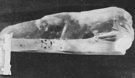
Quartz in its natural condition as mined.
By Frank Kirby
Crystals are used by all broadcasters and many hams to control the frequency
of their respective transmitters. The author tells how these vibrating quartzes
are made.
Perhaps the best place to start an article on crystals is with the raw material
itself. Quartz crystals are found in the United States and often in large size,
but they are usually discolored and contain flaws which make them poor oscillators,
hence most of the raw quartz is imported. The larger part of the imported quartz
comes from South America. The raw or uncut crystal is sold by the pound; and the
larger ones weigh two or three pounds and are seven to eight inches in length. The
larger crystals cost more per pound, but they are more economical to use insofar
as there is less waste in cutting.
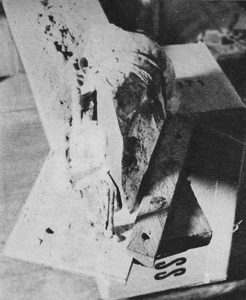
The rough cutting job is first completed. This cut determines
the type.
The muck saw which makes the first and most of the subsequent-cuts.
The crystals are hexagon shaped and are tapered, the taper and slope varying
considerably among different crystals. It is easier to work with a near perfect
crystal because the location of each axis is simplified. For, the person inexperienced
in crystal cutting it is advisable to coat the various surfaces of the crystal with
colored paints in order that they may be readily identified after the crystal has
been cut.
The axes in the crystal are as follows: the "Z" axis runs lengthwise through
the crystal, the "X" axis bisects any of the corners, and the "Y" axis is perpendicular
to any face or side. The sketch shows the various axes and their relation in the
crystal. Oscillating crystals are cut primarily on either of two axes, the "X" or
the "Y." The blanks for the crystals are cut perpendicular to the axis for the cut
of crystal desired, i.e., an X cut crystal would be cut off perpendicular to the
X axis.
A few words now about the advantages and disadvantages of the various cuts should
be in place. The Y cut isn't used much at present unless means is provided to control
its temperature. The frequency of the Y cut crystal changes greatly with temperature
(usually in jumps) and sometimes it stops oscillating completely. Unless especially
ground the Y cut crystal has two main frequencies of oscillation, which in most
cases is a disadvantage, for the frequencies are occasionally close together, thus
making the crystal erratic in operation. The X cut has several advantages over the
Y. The frequency change with temperature change is less than it is with the Y and
the thickness of an X is greater than a Y cut for the same frequency.
Two variations of the Y cut are the "AC" and "AT" cuts. These cuts are obtained
by rotation of the crystal about a line parallel to the X axis either 31 degrees
or 35 degrees, depending on whether one desires maximum output or low drift. In
this instance thin slabs are obtained from which the round crystals will later be
cut. Most of the material to follow will pertain especially to the cutting of round
crystals. [So cut because of cheapness of manufacture. - Ed.] However, the principles
can easily be applied to square ones as well.
In setting up the crystal to cut AT or 35 degree cuts it is possible to cut either
plus or minus 35 degrees from the Z axis, hence it is necessary to test the trial
cut before proceeding further. In the absence of a polarized light source to examine
the crystal the next best bet is to grind one crystal by hand to determine if the
trial cut is the correct one.
Some AT cut crystals are harmonic oscillators, especially on their third harmonic,
that is; with the plate circuit tuned to three times the fundamental of the crystal
it will oscillate on its third harmonic. The output with this mode of oscillation
is fair but the temperature-frequency coefficient is greater than at the fundamental
frequency. The AT cut is the thinnest and the X the thickest of the three mentioned.
Hence it is possible to grind a seven megacycle X cut crystal which will stand up
well under hard usage, whereas, the Y or the AT cut for the same frequency would
be thin and fragile.
Square-cut crystals cost more to produce because a pipe drill cannot be used.
The first operation is cutting the blanks from the raw crystal. If the crystals
are to be round the cuts are taken lengthwise on the desired axis, i.e., the cuts
are parallel to the Z axis for X or Y cuts, the AT cut being an exception. These
slabs are later cut into discs with a special cutter. On the other hand, if the
usual square crystals are desired the crystal is cut up into blocks. These cuts
are made about one inch apart across the crystal perpendicular to the Z axis.
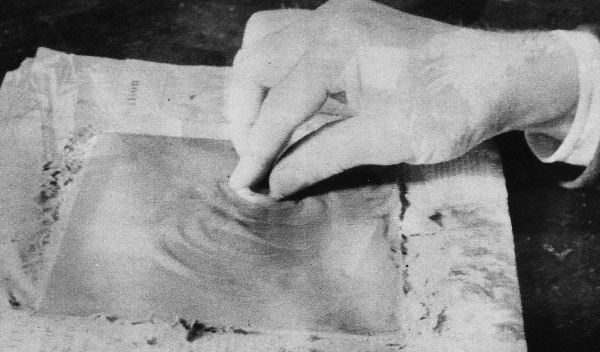
Polishing down high spots on the crystal, by rubbing on plate
glass with a mixture of carborundum and water.
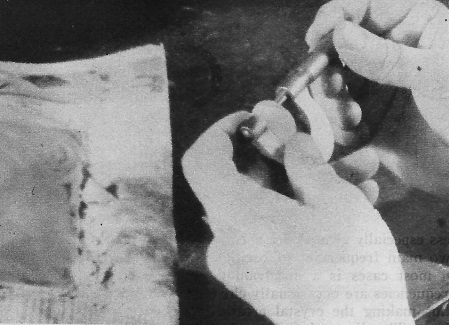
Checking crystal frequency by measuring thickness with micrometer.
Several readings are taken for average thickness.
The cutting of the crystal is done with a muck saw. This saw is a copper disc
of about 16 to 20 gauge and six to ten inches in diameter. The saw runs between
100 and 300 r.p.m. The last mentioned speed is perhaps a little too fast, as this
will cause the cutting abrasive to be thrown from the cut. The cutting abrasive
is a mixture of No. 100 grain carborundum and water, about the consistency of a
thin paste. The paste is thin enough to flow easily into the cut. The soft copper
cuts the quartz because the carborundum which becomes embedded in the muck saw rim.
The copper saw wears quite well and one disc is enough to cut up several crystals.
The saw can also be used for edge grinding crystals. If the saw does not cut well
carborundum is fed to the edge of the saw with a paddle or spoon. Making the bottom
of the cutting mixture box slope toward the wheel also facilitates feeding the carborundum.
Normally when the saw is running it extends down into the cutting mixture about
1/2 inch. The crystal has to be guided a little until the saw starts to cut.
A board is used to hold the crystal during cutting. If the crystal is of irregular
shape and is hard to mount, it is mounted in plaster of Paris and fastened to the
board with pegs of wood. A feeding mechanism facilitates making the cuts all the
same thickness. The threads on the feeding rod are not too fine as to become clogged
with carborundum. A thread of 18 or 20 per inch used.
Cutting the crystal in this manner gives slabs about three by four inches and
of a thickness determined by the finished frequency. These slabs are next fastened
to a flat board with wax or paraffin. This layer of the wax is melted and spread
evenly on the surface of the board with a flame, then the slab is pushed down on
top of the wax while it is still warm. This gives a good firm base for the slab.
The circle cutter consists of a dural cylinder one inch in diameter with about a
1/32 inch wall. Copper or brass could also be used in place of the dural. The cylinder
is fastened to a steel hub with machine screws. The hub has a small diameter shaft
suitable for the drill press to be used. The circle cutter revolves around 300 r.p.m.
or slower. The cutter should be fed slowly and be lifted when it stops cutting to
facilitate feeding in the carborundum. The carborundum if stacked up around the
cylinder will run in of its own accord when the cylinder is lifted or it can be
fed into the cut with a spoon.
Another method to help feed carborundum to the cutter is to slit four cuts parallel
to the axis of the cylinder with a hack saw. When the carborundum is fed in, these
notches fill up and thus maintain the supply of carborundum in the cut longer.
The next step is edge-grinding. This removes all the cracks and nicks. Although
some crystals will oscillate with nicks in the edges it is good practice to remove
them, for in strong oscillation the cracks may spread. The cracks are removed by
edge-grinding by hand on a piece, of flat glass with 300 grain carborundum or, by
machine grinding with a revolving disk or muck saw.
How "X," "Y," or "A" -cut crystals are cut.
Following edge-grinding, a reference face is put on each crystal. This is done
by grinding one face of the crystal. Special effort is made to apply pressure evenly
over the surface of crystal so that the face being ground will grind flat. The crystal
is moved about on the glass in a series of small loops to keep the wear on the plate
glass, on which is being ground, even. A reference face is first put on the crystal
because it will not bend as easily while it is still thick. Of course, the thinner
the crystal the more danger there is of grinding hollows in the reference face.
When the reference face is finished, it is identified, either by sloping one edge
towards the reference face, or by marking it with India ink. If a large number of
crystals are being ground together a reference face is put on each one before going
to the next step.
Next, the crystals are fastened to the grinding plate. A knob in the middle is
used in moving the grinding plate about on the plate glass. The plate is of cast
iron 1/2 inch thick and seven inches in diameter. The plate is heated over a Bunsen
burner and the beeswax allowed to flow evenly over the surface, then the crystals
are pushed firmly down on the plate. This plate is moved about on a large plate
glass with No. 300 grain carborundum as abrasive. The motion is the same as with
the single crystal i.e., in a series of small loops. After about five minutes grinding
the excess carborundum should be washed off, the plate heated to melt the beeswax,
and the crystal positions interchanged. Also during this operation each crystal
is rotated 180 degrees. Allowing the wax to cool again, the grinding process is
repeated. After four or five of such changings examination will show which crystals
are thicker, or which ones are not grinding properly, and they can then be shifted
to more favorable places on the grinding plate. The arrows are placed on the crystals
as a help in rotating and placing them. By careful grinding and placing, and by
sufficient changes, the crystals are ground quite flat; in fact, flat enough for
many of the crystals to oscillate without further grinding. However, as a general
rule, the crystals are usually touched up to secure greater output.
The final touching up and grinding to frequency is done by hand with No. 500
grain carborundum on a fresh piece of plate glass. Care is exercised to see that
no larger grain carborundum is carried over to the finishing plate as a large grain
rolling under a thin crystal would fracture it while it was being finished with
the fine abrasive.
Final grinding is done with the aid of a pair of micrometers, readings being
taken in nine or ten points over the surface of the crystal. These readings are
written down. It can be seen at this point that a reference face is highly desirable.
With thin crystals a cloth is laid on the table under the crystal to prevent accidental
breakage should it be dropped. After the readings are written down a circle is drawn
around the low spots and a cross put on the high ones, thus indicating at a glance
just where grinding is necessary. Overall grinding is accomplished by pressure with
two fingers and the thumb. The high places are ground down by pressure on the spot
with the tip of one finger.
The Y and AT cuts are ground slightly convex; that is, the edges are about 1%
lower than the middle. The X cut is ground flat or for slightly better output slightly
concave (about 1 to 2%). Grinding thick cuts concave is a bit difficult because
the crystal will not bend sufficiently to allow grinding the middle. In the above
case middle is ground down somewhat by grinding over the corner of the plate glass.
While some crystals will oscillate when "out of parallel" by as much as 10% they
are usually ground within 2% of parallel.
RF Cafe began life in 1996 as "RF Tools" in an AOL screen name web space totaling
2 MB. Its primary purpose was to provide me with ready access to commonly needed
formulas and reference material while performing my work as an RF system and circuit
design engineer. The World Wide Web (Internet) was largely an unknown entity at
the time and bandwidth was a scarce commodity. Dial-up modems blazed along at 14.4 kbps
while tying up your telephone line, and a nice lady's voice announced "You've Got
Mail" when a new message arrived...
Copyright 1996 - 2026
All trademarks, copyrights, patents, and other rights of ownership to images
and text used on the RF Cafe website are hereby acknowledged.
All trademarks, copyrights, patents, and other rights of ownership to images
and text used on the RF Cafe website are hereby acknowledged.