|
When I first saw this article
on the "G-Line" transmission system, I thought the cone at each end of the line
was just a gimmick to make it look high-tech. My ignorance of the way the system
works was responsible. As it turns out, the "G-line" transmission medium, named
after inventor
Dr. Georg Goubau, an engineer at the renowned U.S. Army Signal
Corps Engineering Laboratories at Fort Monmouth, NJ, used the cone to transition
a finite radius coaxial cable outer conductor to an infinite radius, sort of virtual,
outer conductor that was free space. Doing so permitted a single line to do the
job of carrying a signal from point A to point B. This significantly reduced the
installation and maintenance cost of deploying a cable-based communications system
- in this case for television broadcasts in areas where over-the-air broadcasts
were nearly impossible. G-line came with many of its own unique issues, and history
shows that ultimately it was not a workable long-term solution.
See also
The G-Line Antenna Lead-In in the April 1955 issue of Radio &
Television News.
The "G-Line" Community TV System
By Robert B. Gary
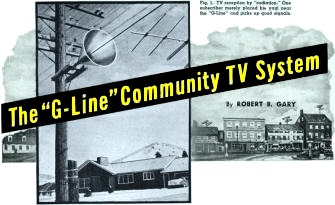
Fig. 1 - TV reception by "radiation." One subscriber merely
placed his Yagi near the "G-Line" and picks up good signals.
The use of a novel transmission line has cut the cost of system installation
and maintenance at Helena, Montana.
The economics of most community TV installations dictate that the operator bring
the TV signal from the antenna to the community before he can start collecting his
installation fees. This means that the initial investment involves the cost of erecting
the antenna and installing the transmission line and its associated amplifiers.
Maintenance of the system is largely confined to the servicing of the amplifiers
and this item is, therefore, a direct function of the distance between the antenna
and the community. This article will describe a new method of bringing the signal
to the community, a method which is far more efficient and economical than the conventional
cable systems.
Coaxial cable has an attenuation on the order of 20 db per 1000 feet on the lower
TV channels. This means that for sound design at least two amplifiers are required
per mile. In addition to the initial cost of the amplifiers and their maintenance,
in many instances a special power cable must be strung to these amplifier sites.
In some localities, therefore, consideration was given to a microwave relay to bring
the TV signal from the mountain to the town. FCC regulations permit public utilities,
like A. T. & T., to lease their microwave facilities to community TV systems
but forbid the community operator installing his own microwave link. As a result,
many community TV installations remain paper projects.
Television reception is not possible in Helena, Montana, but only 15 miles away
is McDonald Pass and the Continental Divide, and channel 13 can be picked up there
from Missoula. By conventional coaxial cable methods the 15-mile haul would cost
$40,000 to $50,000 just for the initial installation.
Helena was fortunate in having Bruce Hamilton, an alert engineer, in charge of
its community TV project. He had read about the "G-Line" and realized that this
technique might solve Helena's transmission problem. After some study and investigation,
Mr. Hamilton started on the project of installing the first "G-Line" in a community
TV system.
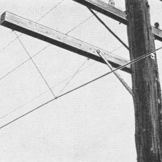
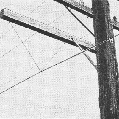
Fig. 2 - The "installation" of the "G-Line" consists. for
the most part. in suspending the line from the cross-arm of a utility pole by a
quarter-inch nylon rope.
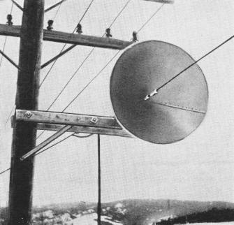
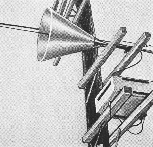
Fig. 3 - One of the "launchers" used in the Helena installation.

Fig. 4 - Nine horns and amplifiers cover the 15-mile stretch.
The "G-Line" is named after its inventor, Dr. Georg Goubau, who developed this
single-wire line for the U.S. Signal Corps. (Details on this line were given in
Leonard Lieberman's article, "The G-Line Antenna Lead-In," in the April 1955 issue
of this magazine). Fundamentally, the characteristics of this line are those of
a coaxial cable of fixed dielectric except that the outer conductor is placed at
infinity. By choosing the proper relationship between the inner conductor and the
surrounding dielectric diameter, the mode of wave propagation is largely axial.
It is only necessary that the single-wire line be fed from a coaxial system by means
of a carefully designed "launcher." This is, effectively, a cone with the center
conductor at its apex and the outer conductor making the transition from the coaxial
cable to the infinite spacing.
Fig. 3 shows a typical "launcher" as used in the Helena installation. The
"G-Line" has some remarkable properties. Its losses at the lower TV channels are
on the order of 10 to 20 db per mile depending on the particular installation. The
installation of the single-wire line is slightly tricky. When the line is about
a half wavelength from the pole or other object, the loss at that point will be
0.05 db. Losses due to bends in the line become appreciable as the corner is made
sharper. Theoretically, the db losses vary with the square of the bending angle
and whenever bends are required they must be as gradual as possible. Another important
characteristic of "G-Line" is that, theoretically, there is very little radiation.
In actual practice Mr. Hamilton found that the radiation from the single-wire line
was a maximum of 1.5 microvolts-per-meter at a distance of ten feet and this was
at a point of greatest signal energy level. This factor is confirmed by the photograph
of Fig. 1, which shows a rather unique method of tapping off a TV line: A home
owner along the route of the "G-Line" simply placed his yagi antenna close to the
wire and got good TV reception. This method "has the operator's sanction since the
regular rental fee is paid by this "radiation subscriber."
The channel 13 signal from Missoula is received by a conventional antenna array
and amplified before it is converted down to channel 4. This conversion was suggested
by the poor performance of the channel 13 strip amplifiers which were tried first.
The "G-Line" itself is more efficient at the higher frequencies but the amplifier
considerations outweighed this feature. For channel 4 transmission, the maximum
diameter of the "launcher" is 58 inches with a taper angle of 45 degrees. The inner
conductor of the "G-Line" is #8 Copperweld and the dielectric is brown pigmented
polyethylene with an outer diameter of 0.253 inch.
Although the theoretical distance from foreign bodies should be on the order
of half a wavelength, for practical reasons the wire was suspended about 15 inches
below the lowest cross-arm of the telephone poles belonging to the Mountain States
Telephone trunk line. In most straight sections the line is suspended by 1/4-inch
nylon rope as shown in Fig. 2. At some bends 15-inch polystyrene rods are used
to brace the line horizontally. The telephone poles from McDonald Pass (altitude
6000 feet) to Helena (3000 feet) predate the road and therefore run along the road
at only a few points. Distances between poles vary and the line crosses the new
U.S. Highway 10 several times. Because power is not readily available at all points
along the line, the line amplifiers are located at unequal intervals and the longest
stretch of "G-line" is about 2.5 miles between amplifiers. On that stretch the total
losses over 2.5 miles are only 53 db.
A total of nine line amplifiers is required to cover the 15-mile stretch. Mr.
Hamilton found it necessary to space the receiving and transmitting launchers about
120-feet apart at the amplifier stations in order to avoid ghosts caused by feedback.
Recent Signal Corps tests seem to indicate that "launchers" can be placed back-to-back
without appreciable separation and it may well be that some mismatch exists in the
Helena system which causes this feedback problem. A typical horn and associated
amplifier are shown in Fig. 4, and it is clearly apparent that the output of
the "launcher" apex goes through the RG-11/U to the conventional line amplifier.
In Helena, the signal is distributed to over 500 homes by means of RG-11/U, double-shielded
coaxial cable and conventional distribution amplifiers. A total of 70 miles of RG-11/U
has been used to date in Helena just to hook up subscribers to the distribution
amplifiers. The installation fee is $125.00 with a monthly tariff of $3.75. The
major initial investment, as in all community TV projects, was the cost of bringing
the signal down from McDonald Pass. While conventional coaxial cable and amplifiers
would have cost at least $40,000, the actual cost of installing the 15 miles of
"G-Line," including the price of the wire itself, the amplifiers, antennas, power
connections, etc., was only slightly over $12,000.
The weather conditions at the Continental Divide are probably the most severe,
with regards to snow and ice, in the country. During the past winter, however, the
signal was lost for only half an hour when an inch of wet snow accumulated on large
portions of the line. As soon as the snow had melted or fallen off, the signal was
restored. Since there is no outer conductor, the problem of moisture seeping in
or condensing between the outer conductor and the dielectric does not exist. The
outer polyethylene jacket has, in other applications, proven to be almost impervious
to weathering for a considerable time.
Helena TV Inc., the operator of this pioneer "G-Line" community TV system, is
licensed by Surface Conduction Inc. of 521 Fifth Avenue, New York, the company which
holds all commercial rights to Dr. Goubau's patents. So successful is the Helena
installation that its owners are now intent on tackling a 27-mile line in the area.
Other community TV systems which are planning to use the "G-Line" include the
Neighborhood TV Corp. of Owen Sound, Ontario. Here the TV signal will be received
at a suitable high point as close to Toronto (150 miles away) as possible and then
transmitted to Owen Sound along the telegraph poles of the Canadian Pacific Railroad.
The most recent application of the "G-Line" to community TV was in September
1956 when an "open wire" transmission line was replaced by a single wire "G-Line"
extending over 8000 feet in the Port Jervis community TV system. Port Video Corporation,
owners of this system, found that this changeover resulted in improved performance.
This new "G-Line" installation extends (apart from poles belonging to General
Telephone and Rockland Light and Power), over system-owned poles separated by 600
feet or more, thus showing the adaptability of the line to varied local conditions.
Posted March 16, 2022
(updated from original post on 4/13/2015)
|