|
Author William Blair lamented in a 1958 issue of Radio & TV News
magazine that helix (aka helical) antennas had not yet been widely adopted
by amateur radio operators despite the advantages they can provide. Helix antennas
are used for transmitting and receiving
circularly polarized electromagnetic waves. An advantage of
using a circularly polarized antenna for receiving is that it is able to make use
of wavefronts arriving at any polarization angle along the propagation axis, thereby
accommodating transmissions at any polarization angle. Theoretically, an ideal antenna
with a particular polarization would not receive a signal arriving at an angle perpendicular
to it, and the strength of any signal would be proportional to the cosine of the
angle of impingement; e.g., cos 0° = 1, cos 30° = 0.866, cos 45° = 0.707, cos 60° = 0.5, cos 90° = 0. Satellite communications is a popular use of helix antennas
because radio signals can undergo an unpredictable amount of rotation as they travel
through the atmosphere. Long distance terrestrial communications can also
benefit from circular polarization since signals can be effectively rotated due
to reflection or even changes in local atmospheric densities. For instance, signals
reflected off of water often assume horizontal polarization regardless of the original
orientation. Intentional radiation in a circularly polarized mode is done with either
a right-hand or left-hand rotation, depending on whether the spiral radiator is wound clockwise
or counterclockwise. Opposite handedness of transmit and receive helical antennas
are mutually exclusive in the same manner as vertical and horizontal transmit and
receive antennas. If helical antennas are so great, then why aren't they used more
often? The physical size required for efficient operation is large compared to other
antenna formats.
Putting the Helix to Work
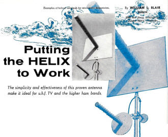
Examples of helical antennas for microwave frequencies. For
information on a 108-mc. helix, see the article "Listening to the Satellites" on
page 44 of this issue.
By William S. Blair, K6QXW
HRB San Diego Laboratories, Solana Beach, California
The simplicity and effectiveness of this proven antenna make it ideal for u.h.f.
TV and the higher ham bands.
The helix is one type of antenna which has not become too popular with amateurs
thus far. This is so because, for frequencies of 144 mc. and below, its dimensions
become large and the antenna is usually unwieldy to handle. (Editor's Note: For
information on a 108-mc. helix, see the article "Listening to the Satellites" on
page 44 of this issue.) However, as more and more amateurs explore the higher frequencies,
the helix may well become "old reliable" in a relatively short period of time.
In planning for operations in the higher amateur bands, enthusiasm mounts quickly
when one begins to list the advantages of the helical antenna. For example: (1)
it has almost uniform characteristics over a broad band (maximum to minimum frequency
ratio approaching 1.8 to 1); (2) gains of 15 db over this band are readily obtainable;
(3) the radiation pattern is a single major lobe with typical half-power beamwidth
of 30 degrees; (4) the dimensions of the helix are not at all critical; (5) it intercepts
either horizontally or vertically polarized waves equally well; and (6) the antenna
is backed by a ground plane and is ideally fed with coaxial cable.
An excellent theoretical discussion on helical antennas is included in the book
"Antennas" by John D. Kraus. However, only the general design equations are necessary
for the construction of practical antennas.
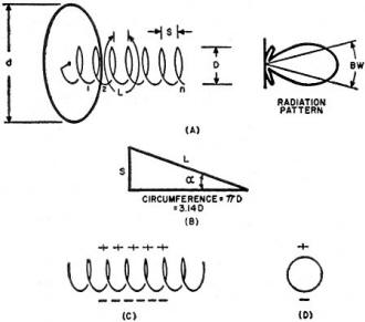
Fig. 1 - (A) Dimensions and radiation pattern. (B) Pitch angle.
(C) Charge distribution. side and (D) end views.
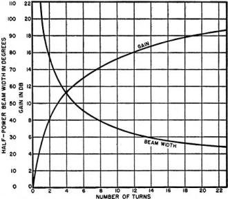
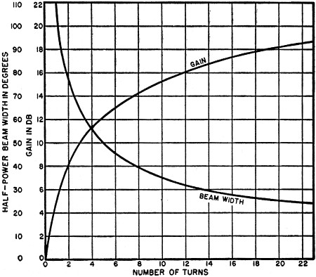
Fig. 2 - Antenna gain and beamwidth shown as a function of the
number of turns, for a helix having a circumference equal to one wavelength along
with a pitch angle of 12.5 degrees.
Fig. 1A indicates the important dimensions of a helix and its ground plane. D
is the diameter of the helix, L the length of one turn, S the distance between turns,
n the number of turns, and d the diameter of the ground plane. If one imagines that
one turn has been unwrapped and laid out flat, the triangle of Fig. 1B results.
The pitch angle α (alpha) is the angle whose tangent is S divided by the circumference
of the helix, πD.
Figs. 1C and 1D show side and end views, respectively, of the helix. The plus
and minus signs indicate an instantaneous distribution of charge for the axial mode
of operation. This is the mode most commonly used and is one which results in a
highly directional radiation pattern. In order that the charge be so distributed,
the circumference must be on the order of one wavelength at the desired operating
frequency. As examples of the latitude permissible in the dimensions, this axial
mode of operation is readily obtained with circumferences between 3/4, and 4/3 of
a wavelength, pitch angles from 12 to 15 degrees, and any number of turns greater
than 3.
Fig. 2 shows how the antenna gain and beam width vary as a function of the number
of turns in the helix. These curves are computed for an ideal helix with a circumference
equal to one free-space wavelength and a pitch angle equal to 12.5 degrees. From
these two values, Fig. 1B shows that the spacing between turns is equal to 0.22
free-space wavelength. It is interesting to note that doubling the number of turns
in the helix results in 3 db greater gain and a reduction in beamwidth by a factor
of 0.707. Generally even for high-frequency antennas, it is not too practical to
build helices with more than about 15 turns since the gain does not increase very
rapidly above this number and support of the structure becomes more of a problem.
In the event that the dimensions of a particular helix are not those used in
calculating the curves, the following approximate equations may be used to determine
gain and beamwidth:
In these equations, Cλ and Sλ are the circumference and turns spacing, respectively,
in wavelengths. They apply only for the axial mode of operation where Cλ is between
3/4 and 4/3, α is between 12 and 15 degrees, and n is greater than 3. Gain
in db may be determined by taking ten times the logarithm of the number obtained
from the first equation. In this equation k: is the radiation efficiency factor.
For the ideal loss-less antenna assumed in the curves, k = 1, but where losses are
present, k is always somewhat less than 1. In approximating the gain of a particular
antenna, the value obtained from the curve should be reduced by 2 to 3 db in order
to account for this factor.
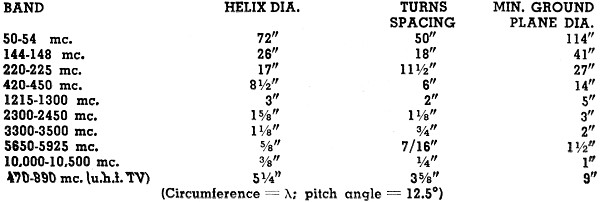
Table 1 gives the dimensions of helical antennas suitable for several of the
higher frequency amateur bands, as well as for the u.h.f. television band. In television,
this type of antenna is especially effective because of its high gain over such
a broad bandwidth. Some amateurs have built helical antennas for the lower ham bands,
but the size of the structures becomes larger as the frequency goes down and rotation
becomes a problem. However, for propagation in one fixed direction this type of
antenna holds out real possibilities. In this case the ground plane would be fabricated
of large mesh screening in order to reduce wind resistance.
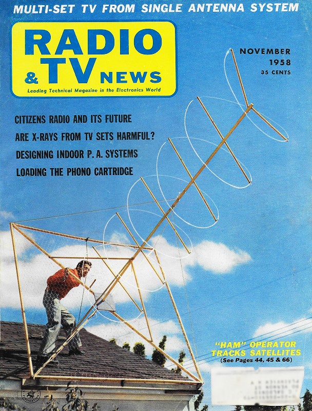
The three antennas shown in the photographs were constructed for operation in
the microwave bands. From the largest to the smallest, the center frequencies are:
1250 mc., 3000 mc., and 10,000 mc. respectively. The two smaller ones were wound
on wooden dowels while the largest one had a hollow 3" cardboard tube for the helix
support. In the latter case, wooden plugs cut from 1/2" plywood were inserted in
the ends of the tube for rigidity.
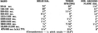
Table 1 - Dimensions of helical antennas for various amateur
and television bands.
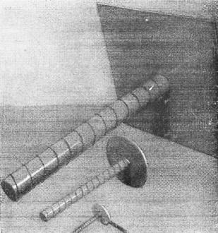
The three helical microwave antennas shown in the lead photo
are displayed here before being mounted on the mast.
In each instance the ground plane was made by fastening sheet aluminum to 1/2"
plywood with wood screws. The diameter of the ground plane is not critical as long
as it is equal to or greater than one-half wavelength at the operating frequency.
A type UG-58/U coax connector was mounted behind the ground plane by means of machine
screws which passed through the plywood and aluminum sheet. Lock washers should
be used under both the heads of the screws and the nuts in order to insure good
electrical contact between the coax shield and the ground plane.
The largest helix was wound with No. 14 solid copper wire while No. 16 bus wire
was used for the two smaller units. A uniform spacing of the turns is easily obtained
by cutting a strip of cardboard as wide as the desired spacing and then winding
it with the wire between turns. If the strip of card-board is not long enough for
the whole helix, it may be advanced as the winding progresses.
The end of the winding is anchored in place by fashioning a small bend in the
end of the wire and inserting it in a small hole appropriately placed at the end
of the tube or dowel. For protection from the weather several coats of Krylon spray-on
plastic and a final coat of paint were applied.
An empirical equation for the antenna impedance, in ohms, is:
R = 140 x circumference in wavelengths
For the preceding examples of helices with circumferences equal to one wavelength,
a 93-ohm coaxial transmission line could be used for a good match. However, for
the antennas pictured, a 75-ohm line was used with excellent results.
Because of the configuration of the helical antenna, the radiation is, in general,
elliptically polarized or, for certain dimensions, circularly polarized. The direction
of rotation of the polarization is either right- or left-handed, depending upon
the direction of the helix winding. This characteristic is fortunate when the helix
is used as a receiving antenna since it will intercept either horizontally or vertically
polarized signals.
For communication between two locations both using helical antennas, it is necessary
that both antennas be wound in the same direction. An electromagnetic wave possessing
one direction of polarization rotation will have a minimum interaction with an antenna
designed for the opposite direction of polarization rotation. It is recommended
that a right-hand sense convention be used for uniformity.
In general, it may be said that the helical antenna is one of the simplest and
most effective beam-type antennas it is possible to make. So, when the day finally
arrives when you get around to firing up those klystrons that came in your big surplus
"buy" - think of the "old reliable" helix and put it to work!
Posted November 6, 2019
|