|
Recently, I posted
from this same 1955 issue of Radio & Television News magazine the article
"Mac's
Service Shop: Magnetic Shielding." Maybe it was a coincidence that it was printed
in the same issue as this article entitled, "Shielding in Hi-Fi Equipment," but
probably not. Discussed here are all three fundamental kinds of fields from which
equipment and/or components might require shielding to prevent cross-coupling of
signals: Magnetostatic, electrostatic, and electromagnetic. An electromagnetic field
is present whenever either a magnetic or electric field is varying since one begets
the other. Different types of shielding materials are required for blocking a magnetic
field versus an electric field, where material permeability and conductivity, respectively,
determines effectiveness. In the era when this was written, most electronic equipment
consisted of leaded (not Pb'd) components interconnected inside a metal chassis
via point-to-point wiring with all combinations of relative orientations so that
opportunities for inductive coupling were legion. Interconnecting power supply and
signal wires ran helter-skelter throughout the maze, further complicating the problem.
Add to that the high voltages used by vacuum tubes and impedance matching and voltage
transformers, and it's a wonder sometimes that anything worked on low level received
signals.
Shielding in Hi-Fi Equipment
 By W. Philbrook By W. Philbrook
Many of the facts covered herein will be helpful when shielding your equipment
for best performance.
At first sight, shielding seems to be a pretty simple little topic, but often
it does not behave quite the way it is expected to, and even some of the more expert
engineers get into difficulties trying to find out why. So there is no need to apologize
for introducing a further article on this deceptively simple subject.
One still meets such questions as: Do you ground both ends of a shielded lead?
Does a magnetic shield need grounding? Should the material for a magnetic shield
have high or low resistance? How important is the permeability of the material?
These are only some of the questions that one encounters. There are other aspects
that are not clearly understood - in particular, why it is that a high grade transformer,
advertised as having a high degree of shielding which checks under test conditions,
seems to have inferior shielding under practical circuit conditions? How is this
discrepancy explained, and can we do something about it?
Let's start by making sure that we have a clear understanding of what constitutes
each of the three basic varieties of shielding.
Magnetic Shield
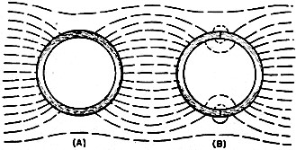
Fig. 1 - How a magnetic shield operates with a steady magnetic
field. (A) Good shielding. (B) Effect of poor magnetic contact causing leakage of
the field. See text.
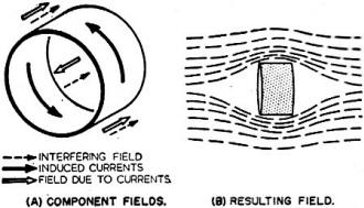
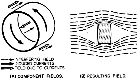
Fig. 2 - How an electromagnetic shield operates with a fluctuating
magnetic field. (A) The relative directions of the interfering field, the induced
current, and the induced field, at one instant during changing sequence. (B) Resulting
field contours.
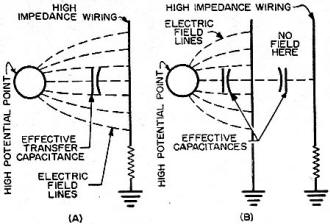
Fig. 3 - How an electrostatic shield intercepts an electric field.
(A) Electric pick-up in the absence of a shield. (B) How the shield intercepts the
electric field.

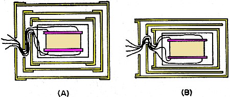
Fig. 4 - Construction of multiple shielding for a transformer.
(A) Ideal construction where each cylinder is complete. (B) Commercial compromise
which has similar properties to (A) for a linear field but not for an asymmetric
field. Refer to article.
A magnetic shield is made of magnetic material. The essential property of the
material is that it should have a very low hysteresis loss. The purpose of the shield
is to capture the magnetic field and lead it around the object to be screened, which
is usually a transformer, without affecting it magnetically.
High permeability is a good thing, but more important is the fact that the hysteresis
should be low. The permeability ensures that the path for the magnetic field is
effectively short-circuited around the object inside the shield. Where the magnetic
field is steady, due to pure d.c., the higher the permeability the smaller will
be the field inside the shield.
But d.c. fields are not usually the cause of worry. It is more important to make
sure that an a.c. magnetic field, such as one radiating from a power transformer
or choke, does not get into an input or interstage transformer. This means that
a fluctuating field must not pass through the shield. When the field fluctuates,
it is important that the magnetic condition of the shield should closely follow
the fluctuations of the magnetic fields.
Hysteresis means that the magnetic condition in the shield is delayed behind
the magnetizing force causing it, and this means that there will be a difference
between the magnetizing force and the short-circuiting effect produced by the magnetic
shield. This difference will reappear as a leakage field inside the shield, so it
doesn't matter how high the permeability of the material is, if it shows appreciable
hysteresis, it will become a poor shield. So a primary requirement is a magnetic
material with extremely low hysteresis.
While on the subject of magnetic field we can answer the question as to whether
the material should have a high or low resistance. Since eddy-current losses are
similar in nature to hysteresis losses in producing a delay in the magnetic field
set up, they will have the same effect of deteriorating the quality of the shield.
This means that a magnetic shield should be of a high-resistance, low-hysteresis-loss
alloy.
The thickness of the shield will have an optimum value too, for any given frequency.
Making the shield thicker will decrease the flux density in the material of the
shield and so reduce hysteresis loss. But, at the same time, it will increase the
path section available for eddy currents, and so increase the component of eddy-current
loss in the shield. At some thickness, for any specified frequency, there will be
an optimum which will provide a maximum reduction in field due to the magnetic shield.
Magnetic shields for input and inter-stage transformers are usually made of Mumetal
or a similar material. An important feature for their satisfactory operation is
that any lids or joints in the shield should be a good close fit so as to provide
a good magnetic contact. Fig. 1A shows how a magnetic field is led around the
shielded space by a magnetic shield, while Fig. 1B shows the effect of a poor
joint at some point in the shield: the reluctance at the joint causes some of the
field carried around to be re-radiated on the inside of the shield.
To answer another of the questions asked at the beginning of this article: does
a magnetic shield need grounding? The answer to this question is: No. A ground connected
to a magnetic shield has no effect upon its magnetic shielding properties. However
it often happens that a subsidiary effect of a magnetic field is to provide static
shielding, which will be discussed later. For this purpose grounding is absolutely
necessary and hence it may be advantageous to ground a magnetic shield so that it
provides static shielding as a subsidiary effect.
It is important in a magnetic shield that there should be no holes or that any
necessary holes in the shield should be as small as possible.
Also, if the Mumetal has to be drilled, or worked on in any manner, after its
pressing, it should be re-annealed after work, so as to operate at the lowest possible
hysteresis loss.
Mumetal and similar materials are not suitable against very strong magnetic fields,
because they saturate at a fairly low flux density. Therefore shields of these materials
are only suitable in magnetic fields where the saturation density of the metal is
not approached.
Magnetic shields are more effective against the lower frequencies, their greatest
effectiveness being against a d.c. field, which is virtually zero frequency.
Electromagnetic Shields
Electromagnetic shielding keeps a magnetic field out by the principle of electromagnetic
induction. It depends on the variation in magnetic field, rather than on eliminating
the magnetic field itself. Consequently it is inherently more effective at higher
frequencies than at low frequencies and is completely ineffective against d.c. fields.
Fig. 2 illustrates the principle. At Fig. 2A the original interfering
field is shown with dotted arrows, the currents induced by the electromagnetic field
are shown by the solid arrows, while the fields due to these induced currents, opposing
the original field inside and aiding it outside, are shown by hollow arrows.
The resulting field around such an electromagnetic shield is shown in Fig. 2B.
The shield is shown open-ended to demonstrate the manner in which the shield works.
In practice, electromagnetic shields may be complete cylinders, with the ends filled
in, in which case they will be equally effective in eliminating fields in any direction.
The circular band shown will only be effective in eliminating fields along the axis
of the cylinder.
For this kind of shield it is important that any lids or joints should make good
electrical contact. There must be no gaps of any kind in the shield and it should
be constructed of a low resistance material such as copper or aluminum. Sheet tinned
iron does not make an effective electromagnetic shield because the iron will not
make a good magnetic shield and its effect on the current in the tin will interfere
with its operation as an electromagnetic shield.
Electrostatic Shielding
This kind of shield does not concern itself with magnetic fields, but with electric
fields. It is intended to keep electric fields out or in as the case may be.
A good ground is essential to the operation of an electrostatic shield, although
this was not vitally necessary to either of the other types. The purpose of an electrostatic
shield is to interpose a grounded shield between two interacting potentials that
might radiate from one to another. Fig. 3 shows the way in which an electrostatic
shield intercepts an electric field.
In an electrostatic shield, provided the material is basically a conducting material
and not an insulator, it is not important for it to have particularly low resistance.
Tinned sheet iron will serve as well as any other material for this purpose, provided
it is not also required to serve as a magnetic or electromagnetic shield.
Applications
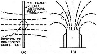
Fig. 5 - How the field used for testing a shielding differs from
practical interference fields. (A) Standard frame producing a symmetrical field
around the test position. (B) A typically distorted field which is often encountered
in practice.
Having differentiated between the various kinds of shield, we can now see how
they may be applied. The first thing to consider is the kind of field against which
shielding is required.
If it is basically a magnetic field, due to a power transformer, a choke, or
a motor, then a magnetic or electromagnetic shield, or a combination of both, will
be necessary to eliminate hum pickup effects.
If, however, we are concerned with a high impedance circuit, in which static
fields due to power line voltages around the place can cause trouble, then electrostatic
shielding is required.
Where a transformer coil is involved, such as an input or an inter-stage transformer,
magnetic or electromagnetic shielding is invariably required. If one of the windings
is high impedance, then electrostatic shielding may also be necessary to protect
the high impedance winding against static pickup.
In circuit wiring, the kind of shielding needed will depend upon the impedance
of the circuit.
Low-impedance circuits, where an interacting magnetic field may induce relatively
large currents, require some kind of shielding to eliminate this effect and, if
a shielded lead is used, its primary purpose is to eliminate the induction of current
in the circuit, rather than to eliminate the effect of static potentials.
In high-impedance circuits it is static potentials, alternating or direct, that
have to be guarded against, and this requires electrostatic shielding.
To return now to the questions asked at the beginning of the article.
Do you ground both ends at a shielded lead? If the shielded lead is intended
solely for protection against electrostatic field, it doesn't matter how many times
it is grounded. But it is also important that the shielded lead should not produce
induction in the lead it is shielding. If there is any difference of potential between
the points at which it is grounded, there will be a current flowing in the shield
due to this difference of potential and this current will produce an induced current
in the lead it is shielding. For this reason it is dangerous to ground both ends
of a shielded lead.
There may be a difference of potential between the ground points to which the
two ends are connected, and if this should occur, the shield will be effective against
electric fields, but at the same time, it will be responsible for injecting, through
electromagnetic induction, another source of interference which may not be present
before both ends are grounded.
Distorted Magnetic Fields

Fig. 6 - Use of a special core construction to combine the functions
of core and shielding. (A) Distribution of interference flux in normal laminated
core. (B) Reduction in center limb using "F" type laminations.
Now we come to the sixty-four dollar question: the one about why measurements
on effective shielding do not line up with practical circuit performance.
Large degrees of shielding are provided by concentric arrangements of either
successive magnetic shields or alternate magnetic and electromagnetic shields, as
shown in Fig. 4. In their best formation each one should be a complete shield
symmetrically spaced from its neighbors as shown in Fig. 4A.
However, practical construction and the economics of production make this rather
expensive to produce and, consequently a compromise such as that shown in Fig. 4B
is used, where a succession of nesting cylinders is used and usually spaced so as
to retain symmetry.
If three such cylinders are used together and each one provides 30 db of
shielding by itself, the over-all shielding should add up to the region of 90 db,
assuming there is no interaction between one shield and the next. This arrangement
may work quite successfully provided the field against which it is shielding is
uniform.
Fortunately for test purposes the specified field is a uniform one, provided
by a number of turns of wire on a framework a foot square, with the shielding under
test placed at the center of the framework. Here the field makes a close approximation
to uniformity and is of accurately predictable field strength.
With a carefully balanced out construction of the simplified variety the shielding
may be quite effective in whichever direction the unit is oriented. However, if
the field is non-uniform, which is far more the usual condition, as for instance
where the field is radiating from a power transformer, shown in Fig. 5B, the
symmetrical distribution of the field through the different shields comprising the
nest will no longer follow, and the asymmetry will tend to exaggerate the transmission
of the field through the combination of shields.
Measurements have shown that under these circumstances sometimes a combination
of shields intended to provide a 30 db-per-stage reduction will provide less
than 30 db for the whole nest, although one stage by itself may still show as much
as a 30 db reduction. This is due to the fact that the outermost shield, being asymmetrical,
distorts the original field further from its original distorted condition and the
successive shields never succeed in getting the field straightened out again.
Combined Core and Shield
An interesting construction providing quite a useful degree of shielding is shown
in Fig. 6. Here, instead of using either of the more usual types of core construction,
the core is built up of "F" laminations so as to provide a single air gap in the
center leg. With the usual construction, either from two different sets of "E" laminations,
or from "E" and "I" laminations, the reluctance, through all three legs of the magnetic
structure is approximately equal, and so any magnetic field reaching the laminations
will divide itself so as to pass a component, of from 1/3 to 1/2 of the total, through
the coil. Using the "F" laminations, there is a low reluctance path each way around
the coil, of approximately equal reluctance, and a high reluctance path through
the center of the coil. Consequently any field reaching the core assembly will be
diverted around the coil.
This construction can be as effective as a complete shield. If this assembly
is then symmetrically mounted in a single further shield, the total shielding is
as effective as two of the more normal types of shield, and has the added advantage
that it does not discriminate against the practical type of non-linear field. In
other words, it gives us results under practical circumstances as good as the test
figures show, which the other constructions often do not.
Posted September 17, 2020
|