|
Amateur radio operators (Hams)
and electronics hobbyists are always on the lookout for a good deal on a good piece
of test equipment (TE). One way to accumulate a budget minded bench of TE is to find
a way to combine the functions of separate pieces to effect a new instrument. This
RF wattmeter was R.A. Thomason's method. It uses a simple application of Ohm's
law for converting electrical current into power values using a bank of high power
resistors and an external ammeter. Hand-dandy conversion charts are provided for
two different values of detector resistors, but the scales could easily be changed
to accommodate any resistor value.
Note that the power dissipating resistor bank is composed of two series-connected
sets of eight parallel-connected 220 Ω resistors, which is 2*(220/8) = 55 Ω.
That represents a VSWR of 1.10:1.
Of course in today's world of inexpensive, good quality (sometimes high quality)
test equipment available online and at swap meets, it would probably cost more to
build one of these from parts, but doing so is a good learning exercise.
I will comment on the poor method used of assembling the resistors as shown with
absolutely no strain relief on the radial leads of the power resistors. Repeated
heating and cooling will almost certainly eventually result in the bodies cracking.
Reducing lead inductance is necessary in order to accommodate high frequency applications,
but going to this extreme is just bad practice.
Inexpensive R.F. Wattmeter
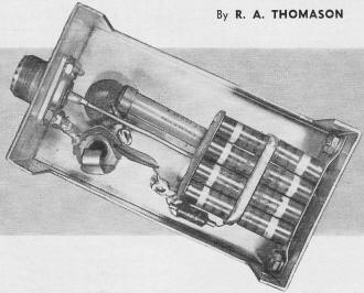
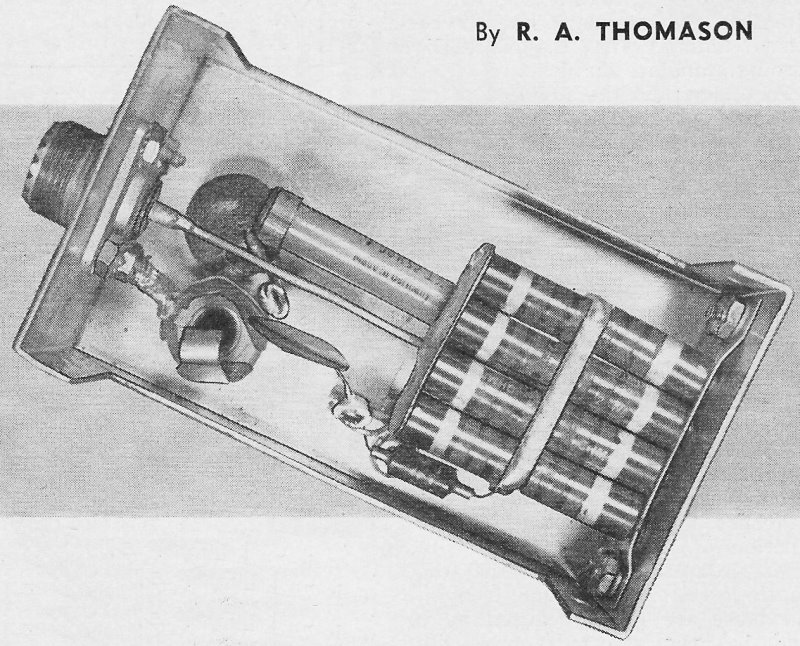
Underchassis view of the wattmeter. The construction of the resistor
bank is critical. Follow the text exactly on this.
By R. A. Thomason
An inexpensive circuit to be used in conjunction with a standard v.o.m. for two-way
communications service work.
Servicing of two-way communications equipment is rapidly becoming an important
source of income to many technicians. The quality of the service the customer demands
on this type of equipment requires a sizable investment in special test instruments
useful only for this type of work. The r.f. wattmeter described here will fill the
need for one of these instruments at moderate cost. It is intended for use in the
following cases:
1. In the shop where a limited amount of two-way service is done, and a more
accurate instrument is not justified.
2. In the field where a minimum of test equipment is carried.
The unit is built into a Bud aluminum "Minibox," and is very compact (4" x 2
1/4" x2 1/4".
A Simpson 260 on the 100 microampere scale is used as an indicator of power.
Other meters could be used here, of course; however, the calibration charts shown
will not apply unless the instrument has the same sensitivity as the Model 260.
The unit would be handier if it had its own meter built-in, calibrated directly
in watts.

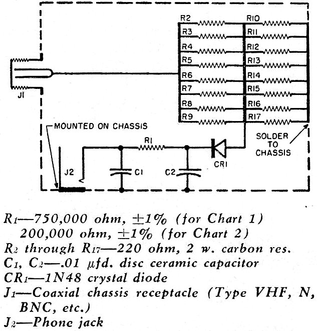
Circuit diagram and parts list for the r.f. wattmeter. The resistors
in the bank must be 2-watt carbon units.
The parts layout can be seen from the photograph and is not critical except for
the resistor bank R2 through R17. These resistors are 220-ohm,
2-watt carbon units. If it is not certain that the resistors selected are carbon,
one should be broken. Wirewound resistors will not work here. In the resistor bank,
the idea is to keep all leads short in order to avoid any inductive reactance. The
bracket is made from four pieces of thin brass shim stock material. Each piece should
be cut about two inches square with eight holes drilled in two columns, using a
#68 drill. Centers are spaced the diameter of one resistor. Two banks of eight resistors
are then made by threading the wires through the shim stock at each end. The wires
are trimmed to about one-quarter inch and bent over. They are then soldered with
a large hot iron, to avoid burning the resistors. The shim stock is trimmed down
to the size of the bank, with the exception of one end which is left large enough
for mounting the completed bank. At least four mounting bolts should be used here.
The two banks are soldered together, being careful not to overheat the resistors.
If it is desired to have the wattmeter cover both ranges as shown in Charts 1
and 2, a switch could be installed to change the value of R1. A switch
with low resistance contacts should be used.
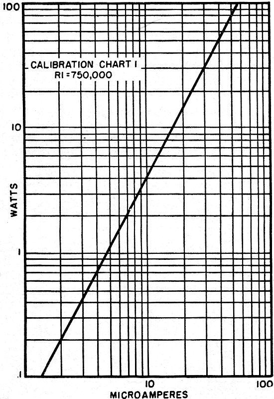
Chart 1 is calibrated up to 100 watts; however, the unit should not be permitted
to operate at the higher powers except for a few seconds at a time since the resistor
bank is only rated at 32 watts.
Several of these units were built and used with different Model 260 meters. The
accuracy held within 10% over a frequency range of 4 to 170 megacycles. If a meter
of known accuracy is available, it should be used to check the accuracy of the charts.


Calibration Chart 1
Calibration Chart 2
Posted March 4, 2019
|