Low Plate-Potential Tubes |
||
Low Plate-Potential Tubes By C. E. AtkinsTung-Sol Electric Incorporated
With the transistor in the output stage, use of these new tubes in auto radios makes possible a vibratorless supply. Re-evaluation of design parameters led to this new family of tubes for direct operation from a 12-volt source. With a compatible power transistor, they make the elimination of vibrator power supplies in automobile radios possible. The development of the transistor by Bardeen, Brattain, and Shockley of Bell Telephone Lab in 1948 started a new phase in the technology of communication and electronic instrumentation. The rapid development of transistors provides many challenging opportunities to achieve results heretofore difficult or impossible with vacuum tubes. Of immediate interest are those applications where the special advantages of the transistor can be most fruitfully employed. A clear-cut example is the hearing-aid field, where the transistor inroad is complete. Another intriguing opportunity is in automobile radios, and this field received early attention from application engineers. Many experimental, and a few commercial, all-transistor automobile sets have been made. They have many good features but are presently expensive and an adequate, economically practical, supply of the varied transistor types needed for volume production of such sets is not yet at hand. Probably the most attractive feature transistors afford in auto-radio design is the chance to eliminate the vibrator power supply. Aside from its cost and the jealously husbanded space it requires, this facility is a cause of considerable field trouble. The car manufacturers rank vibrators No.1 among the components needing attention during the early period of service. Furthermore, in doing its job, the vibrator does not suffer in silence. Vibrator noise which is both mechanical and electrical (in the form of r.f. hash and low-frequency hum) is an irritation to the set designer. His mastery of this problem, often incomplete, also results in minor annoyance to the customer. A single power transistor providing power output levels that are out of the question with vacuum tubes operating at low anode potentials allows one to discard the vibrator power supply; provided the functions of amplification, heterodyning, detection, and automatic gain control can be fulfilled with vacuum tubes at low potentials. Whether provision of such functions was feasible has been a hotly debated subject. Tung-Sol took a lively interest in this matter shortly after March 1952 when the Lamp Department began work on 12-volt sealed-beam lamps. One of the motor car companies had advised it was changing from 6 volts to 12 volts in its automobiles, principally to obtain better ignition, but also to save some copper. Later, the other car companies made the same switch and furthermore adopted the convention of a negative ground connection. In the past, many makes of automobiles had the positive terminal grounded. This lack of standardization would have been awkward. Incidentally, the writer has been unable to rationalize the choice of polarity made by different car manufacturers, in the past, although he has inquired extensively of automotive people. One quaint story was to the effect that a certain ground polarity was required because its opposite caused ground currents returning from the rear axle via the drive-shaft to de-plate the crank-shaft bearings. In any case, the trend just noted opened the way for a realistic consideration of a hybrid receiver employing one power transistor and 4 or 5 vacuum tubes. Most tube engineers were loathe to embark on a tube program for low plate-potential service. There was a history of unhappy consequences whenever set designers tried using tubes at too low an anode potential. For instance, during the war the 6AJ5 was designed in a hurry because the 6AK5 proved unusable in production communication equipment running at 28 volts, even though this type had been used successfully in a pilot run. There was an old rule of thumb to the effect that the mu of a tube must always be less than the plate potential. Operating difficulties were sometimes encountered with triodes having a mu of 100 operating in a.c.-d.c. sets with anode potentials of 80 to 100 volts. If one attempted to use much bias on the tube, the plate current would be cut off. This sometimes happens in practice. Because of this, some engineers expressed the offhand opinion that practical tubes at 12 volts Ep must have an amplification factor, or mu, of less than 10. They felt that, since the grid bias had to be approximately -1 volt (due to contact potential), there would be no plate current if the mu were higher than this value. Although the mu decreases rapidly as the plate voltage is reduced below 20 volts, it is possible to have an appreciable plate current and Gm under these conditions.
Fig. 1 - Change in mu of triode section of the 12AJ6 as plate voltage changes.
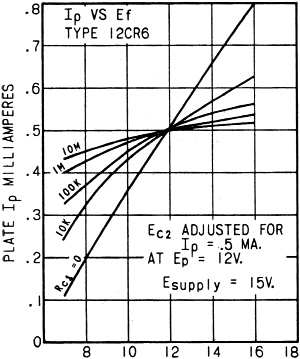
Fig. 2 - Control-grid resistance (RC1) affects change of Ip VB heater voltage. In fact, one is surprised that the Ip is higher than a prediction based on the tube's characteristics at 100 volts would lead one to expect. From inspection of the plate families of the type 12AJ6 (a diode-triode) at high and low plate voltages respectively, it can be seen that the mu, which was 112 at 250 volts, drops to 50 in the neighborhood of 10 volts. Fig. 1 is a dramatic display of this effect, where the mu of the 12AJ6 is shown to drop from 77 to 50 volts Ep to 15 at 1.5 volts Ep. The plate current was held constant at the different values of Ep in taking this data. It is believed the reason for this phenomenon is that, as the grid bias approaches zero, the potential minimum which is normally at or very close to the, cathode moves over in the direction of the grid plane. This changes the effective geometry of the tube, thus lowering the mu. Also, the initial velocities of the emitted electrons are more nearly comparable to the accelerating field due to the plate at these low anode potentials. This undoubtedly modifies the behavior of the tube. Another serious pitfall was thought to be contact potential. Since this would establish the bias at which these low-voltage tubes would operate, many engineers felt that variations of contact potential between different production lots (or during life in the same tube) would seriously affect the performance of any equipment using them. Contact potential had been the villain in many an ill-fated marriage of tube and circuit. However, a deeper insight into the inter-relation between contact potential and other tube parameters revealed how it might be possible to exploit the very feature that generated the apprehension. One facet of this many-sided situation is depicted in Fig. 2. This is a plot of plate current vs heater voltage in the 12CR6. By shifting the screen voltage for each value of control-grid resistor, it is possible to adjust Ip so that it is always .5 ma. with 12 volts on the heater. Hence, all the curves intersect at this point. Note the dramatic difference in slope between the condition of zero grid resistor and that where 10 megohms is employed. Even using 1000 ohms makes a considerable improvement. These phenomena stem from the fact that with higher heater voltage (and consequent greater cathode temperature), more current flows to the No. 1 grid because of the greater velocity possessed by the emitted electrons. Of course, more current will go to the plate and other electrodes as well. If the resistance in the grid-to-cathode path is low, there can be no change in grid potential as the grid current increases. If this grid resistance is high, the grid develops a negative voltage which will increase with increasing cathode temperature. This rising voltage at the grid will prevent the more energetic electrons from reaching the plate. Hence, there is a kind of compensation which, as Fig. 2 shows, tends to hold the plate current more nearly constant. In the same manner Gm and other tube characteristics are leveled out as well. Also, this compensation affords a measure of balance when the effective cathode area or the cathode activity changes. At Tung-Sol, several new tube designs have been evolved embodying this principle. In the composition of a hybrid auto set, there appeared to be these problems the tubes must solve: 1. Driving the power output transistor: This step required a shift from voltage amplification to current amplification, calling for some power output from a vacuum tube. It was estimated this might be as much as 50 milliwatts. 2. Getting gain: Voltage amplification could use either low-impedance or high-impedance circuitry. The earliest endeavors took the form of tubes with larger cathodes giving higher Gm at the price of lower Rp and greater grid-plate capacitance. After some preliminary experimentation, this approach was temporarily side-tracked because the conventional tubes with lower Gm but high Rp and low Cgp appeared to give a quicker answer. Already designed i.f. transformers could be used, and some early sets were made using standard tubes selected for the best low-voltage operation. As a matter of fact, while the design of most of these tubes has undergone considerable revision, one of them, the 12AJ6, remains unchanged. It is merely a 12AV6 with special processing, tested under the low-voltage conditions. 3. The a.g.c. problem: The fact that the input signal at the first r.f. grid is commensurate with the plate voltage posed some new and nasty problems. 4. Stability of gain: Since 12-volt auto sets are expected to function effectively at supply voltage from 10 to 16 volts inclusive, this apparently heroic requirement had to be met. Good life is also required under these conditions. Returning to problem q, the transfer of power, it was felt 50 milliwatts might be needed to drive the transistor. Whether this will remain so depends, of course, upon the power gain of available transistors. In some respects, a suitable driver tube is the keystone of a successful hybrid radio set.
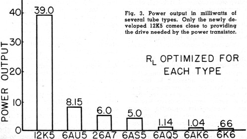
Fig. 3 - Power output in milliwatts of several tube types. Only the newly developed 12K5 comes close to providing the drive needed by the power transistor. As Fig. 3 shows, conventional tubes, even relatively high-power examples, are inadequate to do the job. Only the newly developed 12K5 comes anywhere near the power-output objective. The availability of peak current approaching 40 milliamperes in the vicinity of zero bias - is achieved in the 12K5 by employing the structure depicted in cross-section in Fig. 4. The plate family and transfer characteristics obtained with the special design are shown in Fig. 5. In the 12K5 the space-charge grid principle is employed. This was first disclosed by Langmuir in 1913. By providing a No.1 grid adjacent to the cathode with a positive accelerating potential applied to it and a control grid disposed between this accelerator and the plate, Langmuir was able make tetrodes with very high transconductance. When screen-grid became commercially available after 1926, sporadic efforts were made to this principle in equipment. However, most of the tetrodes and pentodes available to the equipment designer did not operate well under space-charge conditions. Furthermore, it was not good engineering economics to provide the power required by the space-charge grid, as the gain in transconductance did not generally warrant the cost entailed in exploiting it. But in a car radio there is a different kind of logic. Since the voltage is low, it is easily provided by the car-carried battery. The 50 or 100 ma. required for the space-charge grid is minuscule in the overall current needs of the modern automobile. Accordingly, this ancient stratagem, long discarded, was revived for the tube that became the 12K5. The geometry of this type provides a fine-pitch No. 1 grid having 150 turns-per-inch spaced .018" from the cathode, which is fairly large, with an area of 1.8 square centimeters. The grid-to-cathode spacing is generous and poses no manufacturing difficulties. The No. 2 or control grid, having 80 turns-per-inch, is a bit closer to both No. 1 grid and plate. Here the spacing is approximately .012" each way. Holding this configuration is a bit tricky in production. This disposition of elements provides the desired features. It is believed that the fine No.1 grid to which the 10- to 16-volt car-battery potential is applied accelerates the electrons and groups them into thin sheaths. It is well known that the factor that limits current in thermionic devices is the repelling effect of the electrons upon one another when they are crowded together. The provision of a multitude of layers where the space-charge density is low probably helps to achieve high space currents with low applied potentials. In addition to its power-output performance, the 12K5 is an excellent low-voltage relay control tube. It is possible to achieve 8 or 10 ma. of plate current with only 2 volts of plate potential. As mentioned earlier, providing adequate automatic gain control was a real problem. The usual a.g.c. potential has a magnitude comparable to the anode potential of the i.f. amplifier. This is insufficient to protect the No.·1 grid of the first stage against positive excursions on very strong signals. Accordingly, there is bound to be spill-over through the first stage, and this can be sufficient to overload the converter tube. However, designers hit upon the expedient of applying additional a.g.c. voltage to the suppressor grid of the r.f. tube in order to limit the amount of signal getting to the following stage. To do this successfully, certain compromises have been forced on the tube designer.
Fig. 4 - Location of special space-charge or accelerating grid in 12K5 tetrode.
Fig 5 - Characteristics of the 12K5 obtained with construction shown in Fig. 4.
Fig. 6 - Effect of aging on tube characteristics, using type 12AD6 as an example. Characteristics of partially aged tube is shown in (A), of fully aged tube in (B) With high impedance i.f. transformers, it is necessary that the amplifier tube have a correspondingly high dynamic plate resistance (Rp). This has been difficult to achieve in tubes operating at low anode potentials. The beam-forming plates and suppressor grids, which are effective in high potential devices, do not give the same favorable results with operating potentials in the region of 10 to 15 volts. In fact, the suppressor grids employed in these hybrid r.f. tubes are probably more useful in reducing the control-grid-to-plate capacity than they are in providing effective suppression. The Rp of a tetrode is considerably influenced by secondary emission from the anode. These secondary electrons leave the plate and are collected by the screen grid. Since the magnitude of this effect is sensitive to the applied potentials, a condition exists whereby small increments of anode potential can cause either a drop in plate current or too rapid a rise in plate current. In the latter case, Rp will be too low whereas, in the former case, it will be negative. Either of these effects can be harmful. On many tubes it was found that a nice balance between negative and positive Rp along the plate volt-ampere curve resulted in Rp values which were astonishingly high (several megohms where, without this effect, the Rp would have been a few hundred-thousand ohms). This dip in the characteristic is shown in the curves for the 12AD6 in Fig. 6A. Those readers who are old enough to remember the early screen-grid tetrodes (type 24A), will recognize this shape as the dynatron kink. Pentodes were introduced to cope with this characteristic. A coarse-pitch No. 3 grid placed between the screen grid and the plate served to thwart the return of electrons from plate to screen. Because of the geometry involved, this grid did not adversely affect the flow of primary electrons to the plate to any great extent. As stated earlier, suppressor-grid techniques do not function as well with tubes at low voltages. While suppressor grids are still used in the hybrid-set tube designs, it is mainly to help reduce the grid-plate capacity and because this grid is sometimes needed to secure adequate a.g.c. It was found necessary to rely on special materials and processing in order to iron out the plate characteristic and secure the needed control over the Rp The efficacy of these measures is greatly facilitated by the important fact that these tubes are used at very low voltages, so that there is very little plate or screen dissipation. The heat developed by the electrodes in more conventional operation has the effect of disturbing or destroying any surface film left on the electrodes by special processing. In contrast, it is possible to obtain stability and long life at low voltages with special surfaces too fragile to long endure under the conditions of high voltage operation. Fig. 6B shows the change in the plate characteristic of the same tube depicted in Fig. 6A after it received special aging. To gain a partial understanding of these phenomena, reference is made to an article by Matheson and Nergaard in the RCA Review, June 1951, entitled "High-Speed Ten-Volt Effect." This is a study of the behavior of anode currents in thermionic diodes with oxide-coated cathodes, operating with plate voltages in the region of 10 volts. In an ideal space-charge limited diode the current is proportional to the 3/2 power of the applied voltage. It was noted, however, that in the neighborhood of 10 volts, there was a small deviation from this 3/2 power. This was found only in diodes with an oxide-coated cathode. Experiments performed to discover the cause in the coating itself gave negative results, so a study was made of the anode. An experiment was performed wherein an anode which had not previously been exposed to the cathode was rotated in place of one that had been in position when the cathode was broken down and activated. This new anode did not exhibit the 10-volt effect until after some time. The effect was then explained by the fact that a layer of barium from the hot cathode had condensed on the anode, thus giving rise to secondary emission. This phenomenon is, of course, applicable to triodes and tetrodes - or pentodes. The effect is manifested by the erratic change of Rp as the critical plate voltage is approached. From the foregoing, one might think that this reflection of electrons - if such it is - might be eliminated by providing the anode with an especially clean naked surface. This has not proved feasible because it is hard to long maintain such surfaces in operating vacuum tubes. It has so far not been possible to make good tubes with bright nickel plates. If, however, carbonized nickel is used and the device is processed in such a way that there is probably a layer of cathode constituents on top of this carbon coating, a composite surface is achieved which seems to be quite effective in curtailing reflected electrons. This situation is analogous to that obtained when an optical lens or prism is coated with a thin film in order to increase light transmission by reducing reflection from the surface. To comprehend this parallel, you must recall that deBroglie in 1924 advanced the theory that electrons had wave properties as well as the particle characteristics assigned to them. This was verified experimentally by Davisson and Germer in 1927. According to this theory, electrons have an associated wavelength which varies inversely as the speed with which they are traveling. Since 10-volt electrons proceed rather slowly, their wavelength is rather long as such things go. This wavelength is on the order of 3 or 4 angstrom units. This is of the same relative magnitude as the film thickness discussed in connection with the plate. With this state of affairs, it is credible that there is a relation between the deBroglie wavelength of the slow-moving electrons and the refraction characteristics of the various media these electrons move through when they impinge on the plate. The writer believes some such machinery operates to curtail reflection which, in turn, makes possible better control of Rp at these low operating voltages. Thus, by using processing techniques not generally suited to vacuum tubes intended for conventional higher-voltage service, and by altering the electrode geometry to take advantage of contact-potential bias, Tung-Sol's engineers have designed a set of tubes that effectively perform with all electrodes energized by the 12-volt car battery. With a suitable power transistor, this makes possible an automobile radio without a vibrator power supply. These tubes are not final in any sense. The writer believes many more and better types will be developed by the tube industry for this class of service before the day of the all-transistor car radio arrives. In the development of these tubes, many engineers made worthwhile contributions. The program owes a special debt to Mr. Fred Crawford of the Tung-Sol design department for many important contributions, especially in the field of tube processing.
Posted December 29, 2021 |
||
")
")