|
Try Googling 'cyclodos' and 'cyclophone'
and see what you come up with. I found that
Cyclodos (see Facebook)
is a German company which makes apparel from recycled inner tubes and tents (among
other things), and
cyclophone is a weird bicycle-mounted contraption for blasting
sound while peddling down the street. In 1946 when this article appeared in
Radio News magazine, the terms cyclodos and cyclophone referred to modulator
and demodulator tubes, respectively, for pulse-time modulation applications. Fortunately,
the science of pulse modulation quickly evolved past such devices. This article
goes into quite a lot of detail on the beginnings of pulse modulation techniques
developed for radar systems during World War II. It is very informative
without going into the gory details of equations that govern the theory.
A simple analysis of a wartime development which will have widespread ham application
in the u.h.f. and s.h.f. bands.
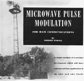
Fig. 1 - Signal Corps 4500 mc, eight-channel pulse transmission
equipment, showing all spare and operating components and antenna, set up for field
operation.
By Robert Endall
In the past, radio amateurs have always been in the forefront of technical progress
in experimental communication on the higher frequencies, and many of the advances
in high-frequency communication are traceable directly to amateur activity. Before
the war many hams were spending much of their time on the 56- and 112-mc. bands
and experimenting with higher frequencies. Wartime progress has so greatly extended
the radio frequency spectrum that communication frequencies are now regularly assigned
and may be expected to carry useful traffic up to 30,000 mc. Many radio amateurs,
especially those who have for the past five years been active in wartime u.h.f.
and microwave research, will now want to go on the air at carrier frequencies well
up in the microwave region.
The cost of ultra-high frequency equipment, the expense of tubes for generating
microwave power, and the difficulty of modulating at u.h.f., have up to now been
a handicap to widespread amateur experimentation on these frequencies. The intensive
military program of development and production of high frequency equipment has done
much to eliminate these difficulties. The application of mass production techniques
has greatly decreased the expense of equipment.
The development of disc-seal tubes, magnetrons and klystrons, has greatly simplified
the problem of generating microwaves. Now the new technique of pulse-time modulation,
which has recently been removed from the secret list by military authorities, introduces
a considerable simplification in the problem of modulating microwave transmissions.
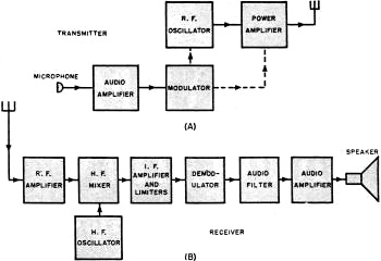
Fig. 2 - Block diagrams of conventional type of transmitter
and receiver that may be used for any type of modulation. (A) transmitter. (B) receiver.
A pulse-time-modulated carrier consists of signals of the simplest type - short
pulses of r.f. having constant shape and amplitude with variable timing. Because
of bandwidth considerations, this type of modulation has its maximum usefulness
at microwave frequencies. Although developed primarily for commercial multiplex
telephone transmission, pulse-time modulation has distinct advantages which suit
it particularly well to amateur communications:
1. Since the carrier is modulated only by being switched on or off to create
the pulses, the circuit can be of an extreme simplicity of design not possible with
other systems.
2. By making full use of the much wider bands per channel which are not only
available, but definitely preferable, at the higher frequencies, this system makes
it possible to reduce considerably the influence of parasites of artificial origin
and to increase considerably signal-to-noise ratio.
3. Higher peak power and much higher frequencies are attainable than would otherwise
be possible because of limitations due to heating of the transmitter tubes.
Thus, at the same time that it effects economy in transmission and simplifies
and improves the efficiency of reception, pulse-time modulation provides also a
greater degree of static reduction in communication.
In addition, the multiplex properties of pulse-time modulation open up still
another application for amateur communication in helping to overcome line-of-sight
difficulties to some extent The transmitted pulses are of very short duration and
separated by comparatively large spaces, therefore more than one telephone channel
may be transmitted on the same carrier provided that the pulses are suitably displaced
with respect to one another. It is quite conceivable that by making use of this
factor, amateurs may cooperate in setting up long nets and relay systems by means
of which each operator will be conducting his own conversation and acting as a relay
point for as many as eight or ten other conversations taking place over distances
far beyond the limitations of ordinary line-of-sight communication.
Theory of Pulse-time Modulation
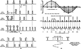
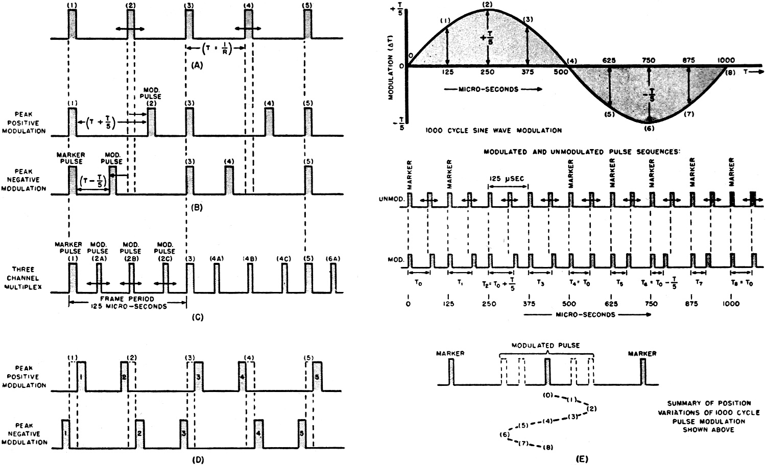
Fig. 3 - Methods of pulse-time modulation. Intelligence
is transmitted by r.f. pulses having constant amplitude and duration.
The basic theory of pulse-time modulation is extremely simple. It consists of
transmitting intelligence by pulses of r.f. having constant amplitude and duration,
the instantaneous amplitude of the voice being translated into variation of time
intervals between successive pulses. The rate of this variation corresponds to the
instantaneous frequency of the signal. The pulses themselves are of very short duration,
separated by comparatively large spaces.
The spacing between the successive pulses can be varied in a number of different
ways. Two of these possible methods of position-variation which have been used in
practice are of interest to amateurs, and will be described.
The unmodulated carrier, consisting of a series of pulses having a constant repetition
rate, is shown in (A) of Fig. 3. The individual pulses may be designated by
numbers 1, 2, 3, 4, 5, etc., and the pulse repetition rate R per second. Then the
time interval between successive pulses is T = 1/R seconds. When modulation is applied,
the timing between the pulses is varied by an amount proportional to the modulating
voltage, and at a rate corresponding to the frequency of the modulating signal.
In the first type of time modulation, one set of pulses is kept fixed in its
time position and serves as a reference set for the time modulation of the other
pulses. For instance, in Fig. 3A and 3B it can be seen that the odd-numbered
pulses 1, 3, 5, etc., always remain in the same position under one another, while
the position of the even-numbered pulses 2, 4, 6, etc., varies. The fixed pulses
are the reference (or marker) pulses, and the others are modulated in position with
reference to them. Fig. 3B illustrates the pulse position relationships for
a single-channel system having a peak modulation of T/5. As shown in the upper part
of the diagram, the distance between the modulated pulse and the marker is increased
for positive modulation; the lower figure in diagram B shows the corresponding decrease
in distance between modulated and marker pulse for peak negative modulation.

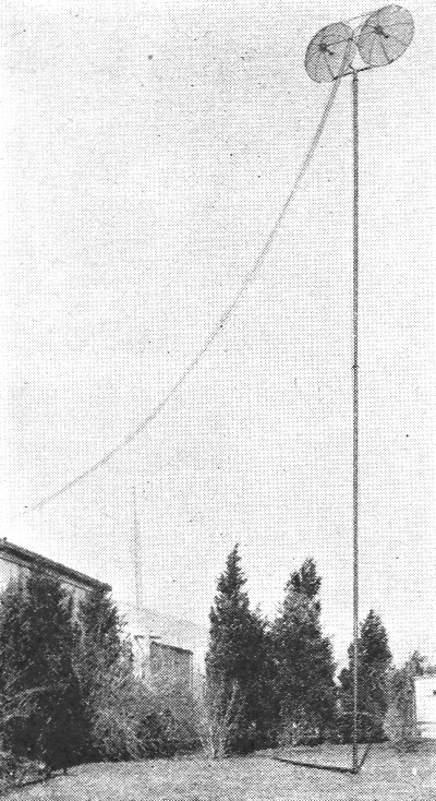
Fig. 4 - Antenna system used in conjunction with equipment
illustrated in Fig. 5.
The process of modulation may be better understood by reference to Fig. 3E,
which shows the pulse-position relationships when the single-channel system is modulated
by one complete cycle of a 1000-cycle sine wave. During the positive half-cycle
the pulse spacing is increased, as shown, by amounts varying from zero to T/5 according
to the modulating voltage; while during the negative half-cycle of modulating voltage
the spacing is decreased by amounts varying from zero to T/5. A comparison between
pulse positions for the modulated and unmodulated condition can be seen in the middle
diagram of Fig.3E, which shows the pulse sequence through a complete position-modulated
cycle. The position variations of the modulated pulse for the 1000-cycle modulation
are shown in summarized form in the lower figure, which shows the various positions
of the pulse at different times in the modulation cycle. A system of the type shown,
having a frame period of 125 microseconds (i.e., repetition frequency of 8000 cycles),
is capable of transmitting a telephone channel of 3000 cycles.
(This system may be used for multiplex transmission in the manner shown in Fig. 3C.
In this case the same marker pulses and the same frame period are used as in the
single-channel system just described, but for each marker pulse there are now three
modulated pulses each capable of carrying its own independent modulation. Thus,
when the B pulses are modulated, the distance between the B pulses and the marker
is varied within its limits regardless of the instantaneous position of the A and
C pulses. Likewise the positions of the A and of the C pulses are varied regardless
of the other channels. In the system illustrated, the A pulses constitute channel
I, the B pulses channel II, and the C pulses channel III. When multiplex transmission
is used, the marker pulse is made wider than the others, as illustrated, in order
to distinguish it from the channel pulses.)
The second type of pulse-time modulation does not make use of a fixed series
of pulses. Instead, the pulses are divided into pairs, and the timing between the
two pulses of each set varied in accordance with the modulating voltage. Thus, pulses
1 and 2 would be one pair, 3 and 4 another, 5 and 6, etc. For the condition of peak
positive modulation as shown in the upper part of Fig. 3D, these pairs are
moved closer together while the pairs of pulses 2 and 3, 4 and 5, 6 and 7, etc.,
are moved farther apart by an equal amount. For the condition of peak negative modulation
as shown in the lower part of the diagram, the situation is exactly reversed. Pulses
1 and 2, 3 and 4, etc., are moved farther apart while 2 and 3, 4 and 5, etc., are
brought closer together. There is no change in the average pulse rate.
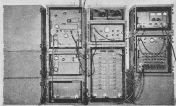
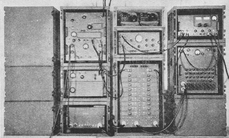
Fig. 5 - Signal Corps 1400 mc. pulse-time modulation equipment
for transmitting and receiving eight independent telephone channels simultaneously.
The photograph shows all operating and spare components in place.
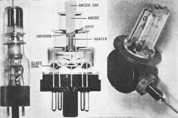
Fig. 6 - Tubes for generating receiver beat oscillations and microwave power.
(Left) Klystron. (Center) Disc-seal (lighthouse) tube. (Right) Magnetron.
In pulse-time modulation systems the exact shape, duration or amplitude of the
pulse has no fundamental importance, although it does affect the signal-to-noise
ratio of the system. As in the case of a frequency-modulated system, the amplitudes
are made uniform in the receiver by an amplitude-limiting circuit, thus making possible
a considerable reduction in noise on the sole condition that the maximum potential
due to noise is lower by a certain amount than the maximum amplitude of the received
pulses. (In fact, even if the noise amplitude is greater than the signal pulse amplitude,
there is still the possibility of time modulating during part of the pulse interval
only, and of eliminating the majority of the interference by blocking the receiver
except during the extremely short interval when the pulses are actually transmitted.)
Any noise small enough in amplitude to be eliminated by the limiters will nevertheless
generate an audible noise at the output of the demodulator, because it also has
the effect of advancing or retarding the time position of the leading edge of the
desired pulse. This effect is decreased as the steepness of the wave front of the
transmitted pulse is increased.
Since both the required bandwidth and the signal-to-noise ratio are determined
by the steepness of rise of the transmitted pulse, it is thus possible to strike
the best compromise between bandwidth, noise, and receiver-oscillator stability
to make most effective use of the high-frequency bands.
Pulse-Time-Modulation Circuits
A number of the circuits which have been developed for time-modulated pulse transmission
and reception are of interest to radio amateurs from the viewpoint of experimental
communication on the microwave frequencies. Some of these circuits can be used with
very little modification, while others can easily be adapted to make them reasonably
inexpensive and suitable for ham use. A brief consideration of the existing circuits
will serve to illustrate how amateurs can use them for experimental microwave communication,
and how they may go about designing their own circuits for high-frequency pulse
communication.
The principles of pulse-modulation transmitters and receivers can best be understood
by considering them from the viewpoint of the basic principles of radio transmitter
and receiver design. Fig. 2 shows block diagrams giving the essential details
of the most general types of transmitter and receiver. These block diagrams apply
to all three types of modulation now in general use - amplitude modulation, frequency
modulation, and pulse-time modulation.
For any type of modulation, the transmitter consists essentially of the following
sections: (a) an audio amplifier, (b) the modulator, (c) a high-frequency oscillator
for generating the carrier, (d) a radio-frequency power amplifier. The receiver
can be divided into the following sections: (a) a radio-frequency amplifier, (b)
a high-frequency local oscillator and converter, (c) an intermediate-frequency amplifier
and a series of limiters, (d) a converter or demodulator to restore the audio characteristics
of the original signal, (e) audio filters and an audio amplifier to bring the signal
to the desired level. In u.h.f. receivers, the r.f. amplifier (a) is generally omitted
and the signal from the antenna fed directly to the high-frequency mixer.
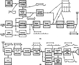
Fig. 7 - Block diagram of a pulse-time modulation transmitter
(A) and pulse time modulation receiver (B), using only conventional type tubes.

Fig. 8 - (A) Schematic diagram of pulse-time transmitter
modulating circuit. (B) Diagram of pulse-time receiver demodulating circuit.
The circuits for the three types of modulation differ from one another primarily
in the modulating and demodulating circuits, and in the manner in which the modulation
is applied to the output stage of the transmitter. In an AM transmitter, the modulation
is generally applied to the power amplifier or to an intermediate power amplifier.
In an FM transmitter, the modulation is applied before the power amplifier to the
r.f. oscillator, whose frequency is caused to vary by an amount proportional to
the instantaneous audio amplitude. A pulse-time modulated transmitter uses no power
amplifier, the oscillator supplying the carrier power directly to the antenna. The
modulator in this system serves the function of converting the audio amplitude into
time-modulated pulses, which are applied to either the grid or plate circuit of
the power oscillator so that the carrier is generated in short position-modulated
pulses.
The essential difference between AM receivers and receivers for FM and pulse-time
modulation is in the use of limiters. The AM receiver is a linear system as regards
both the audio signal and the noise input, whereas the use of limiters in FM and
pulse-time modulation receivers makes possible a considerable reduction in the noise
output. Pulse-time modulation possesses the further advantage that oscillator tuning
and stability are much less critical than in FM reception.
Modulation and demodulation, which is where pulse-time communication differs
basically from AM and FM, may be accomplished by many different methods:
(a) One pulse-time system of the first type - ie., using a fixed series of marker
pulses - makes use of two tubes, known as the "cyclodos" and the "cyclophone," developed
specifically for this purpose. The essential features of these tubes are shown schematically
in Fig. 10. Both tubes make use of an electron beam which, by means of an
ordinary circular sweep circuit, is made to strike the aperture plate in a circular
path. (For ordinary telephone communication, 8000 revolutions per second is a suitable
frequency of rotation for the electron beam.) The aperture plate contains radial
slits, so that during the time the beam is passing each slit the electrons go through
and strike the collector segments, while at all other times they are intercepted
by the aperture plate. Thus, once in each complete rotation of the electron beam
a short pulse of current is passed to each collector segment. The tubes shown in
the diagram, having aperture plates with four slits, would be suitable for a multiplex
system having three channels, one slit serving for the marker pulse and the others
for the three time-modulated signals.
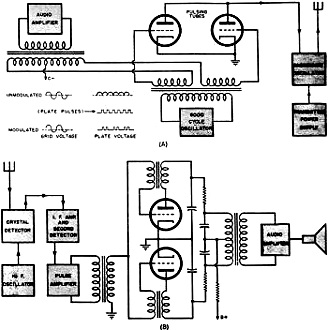
Fig. 9 - Transmitter (A) and receiver (B) for time-modulated
pairs of pulses.
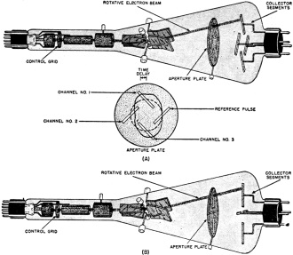
Fig. 10 - Artist's illustration of the cyclodos tube (A)
and the cyclophone (B).
In the modulating tube (the cyclodos) the slits are placed at an angle to the
radius of the circular plate, as shown in Fig. 10A. It can be seen from the
diagram that because the slits are tilted at an angle, the time when the beam crosses
the open slit changes either forward or backward as the radius of rotation of the
beam changes. Thus, audio-frequency amplitude variations may be converted into pulse-time
variations by varying the instantaneous voltage on the deflecting plates and thereby
changing the radius of rotation of the electron beam. The dotted circle in Fig. 10A
represents the circular pattern obtained when all three channels are unmodulated.
The solid path represents modulation in all three channels - instantaneous peak
positive modulation in channels 1 and 3, negative modulation in channel 2. (The
marker pulse, of course, is always unmodulated.)
In the demodulator tube (the cyclophone) shown in Fig. 10B, the slits are
placed along the radius of the circular aperture plate instead of being tilted.
To convert the time-modulated pulses into amplitude variations, the electron beam
is made to rotate in a circular path, but the control grid is kept sufficiently,
negative so that the beam is normally cut off except when one of the time-modulated
pulses arrives. The pulses are applied to the grid and, depending upon where the
electron beam is directed with respect to the slit at the time when the unblocking
pulse arrives, there will be a variation in the amount of beam current passing through
the slit and reaching the collector segment.
At the present time the cyclodos and cyclophone tubes are not commercially available.
When they do become available the cost of the tubes, although expected to be moderate,
will be a factor in determining their suitability for amateur use. For the time
being, a reasonable substitute can possibly be improvised for amateur service by
making use of an ordinary cathode-ray tube and phototube arrangement. This can be
accomplished by cutting slits in a piece of black cardboard which fits over the
face of the cathode-ray tube. Light shields and phototubes are placed in front of
the slits so that each phototube records the light coming through one slit. In this
manner, the slotted piece of black cardboard is made to act as an aperture plate
and the phototubes take the place of the electron-collecting segments.
(b) A method of accomplishing pulse-time transmission and reception without requiring
the use of the cyclodos and cyclophone is shown in Figs. 7 and 8. A block diagram
explaining the operation of the transmitter is shown in Fig. 7A with the basic
details of the modulating circuit - the oscillator clipper, the marker pulse generator,
and the pulse position modulator - given in greater detail in Fig. 8A. The
recurrence frequency is determined by the 8000-cycle oscillator, which at the same
time provides a waveform suitable for starting the marker pulse generator and the
pulse position modulator circuits for each channel. The marker pulse is obtained
from the 8000-cycle sine wave by means of the oscillator clipper and the marker
pulse generator. The pulse position modulator consists of a double triode connected
as a biased multivibrator, and a single triode used as a pulse generator. Its operation
may be explained briefly as follows: /p>
In the normal state (represented by the upper set of voltage values in the schematic)
the second section of the multivibrator conducts current. The application of the
marker pulse causes the first section to become conducting and the second section
non-conducting, even after the initiating pulse has ceased. This condition persists
until current flowing through the 3.3 megohm resistor charges the coupling condenser
sufficiently to permit the plate current to flow in this section of the tube, at
which point a rapid reversal takes place. Modulation is produced by variation of
the potential to which the 3.3 megohm grid resistor is connected, by connecting
it to the output of an audio amplifier tube. The mean length of the square wave
generated by the multivibrator is adjusted to place the channel pulse in its nor-mal
unmodulated position by means of the variable load resistor in the plate circuit,
which adjusts the time constant of the multivibrator. The transient in the pulse
generator tube when the reversal takes place causes the position-modulated pulse,
by pulsing into one-half cycle of oscillation the tuned circuit formed by the inductance
L, and the input capacity of the following tube. The remaining features of the transmitting
circuit are quite conventional, as can be seen from the block diagram.
The operation of the receiver circuit can be understood from the block diagram
in Fig. 7B and the demodulator schematic in Fig. 8B. The pulse position
modulation is converted to amplitude variation by first converting it to pulse length
modulation, then filtering out the voice frequencies below 3000 cycles from the
pulse length-modulated signal. This conversion is accomplished by means of a multivibrator
circuit. For each multiplexed channel there is a gate pulse which is generated in
a fixed relationship to the marker pulse, as shown. When the voltage of the modulation
pulse is superimposed on the gate pulse, the multivibrator is triggered and remains
operative until the end of the gate pulse interval. This results in an output square
wave whose leading edge is varied at the voice frequency. The remaining features
of the receiver circuit are quite conventional, as can be seen from Fig. 7B.
The circuits for pulse-time modulation and demodulation employing conventional
tubes are seen to be somewhat more complicated than those making use of the cyclodos
and cyclophone tubes, especially for multiplex communication. However, for single-channel
operation the circuit is not too complex, and it has the advantage of using standard
tubes which are readily available. At the same time, it affords the radio amateur
an interesting opportunity to experiment with extremely useful pulse and non-standard
waveform techniques.
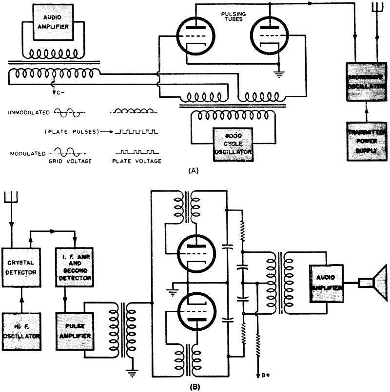
(c) Circuits for pulse transmission and reception by variation of the timing
between pairs of pulses without the use of a reference pulse are shown in Fig. 9.
In the transmitting circuit the pulses are generated by connecting the grids of
the pulsing tubes in push-pull, and the plates in parallel. The manner in which
the pulsing and pulse timing is accomplished can be seen from the wave-shapes shown
in the diagram. With no modulation applied, one or the other of the pulsing tubes
passes current at all times except when the input from the constant-frequency source
is near the zero value. For near zero values, both tubes are simultaneously cut
off and a short pulse of relatively high potential is passed into the transmitter.
With no modulation these pulses are uniformly spaced. When modulation is applied
the bias potential of both grids is varied in opposite directions, thus drawing
alternate pulses together. Reversing the polarity of the modulation potential causes
the pulses to be pushed apart.
The demodulator in the receiver makes use of two pulsing oscillators of the type
used to produce sawtooth potentials in television receivers, each adjusted to the
same frequency as the oscillator in the transmitter, with a common plate resistor
to make them tend to operate 180° out of phase. The received pulses synchronize
the operation of the oscillators, alternate pulses controlling each oscillator.
Thus, when a received pulse advances the pulse of one oscillator, it retards the
pulse of the other. Since the received pulses modulate the phase or timing of the
oscillations of each pulse oscillator, but not the frequency, they vary the average
current through the tubes. Therefore once the oscillators have dropped into synchronism
with the received pulses, the average plate current will be modulated by the pulse
modulation. This provides the original audio signal which was transmitted.
From the above discussion of the theory of pulse-time modulation and from the
circuits that have been described, the amateur who desires to experiment in microwave
communication should be able to design and construct a pulse-time modulation rig
to use on these frequencies.
Posted April 25, 2022
(updated from original post on 3/16/2015)
|