|
While this article is directed
at amateur radio operators who want to explore working in the microwave bands, it
is good fodder for anyone who wants a fundamental introduction to waveguides, resonant
cavities, distributed elements, and atmospheric propagation. If that describes you,
and particularly if you have formulaphobia, then start reading. Even though the
article appeared in a 1952 issue of Radio & Television News, the list
of frequency band allocations are not much different than today so the information
is useful. Unknown to many is that in the early part of the last century Amateurs
pioneered the use of microwave bands when the Federal Communications Commission
(FCC) allocated the spectrum to them since many "experts" considered it unusable.
Microwaves for the "Ham"
By Samuel Freedman, W6YUG
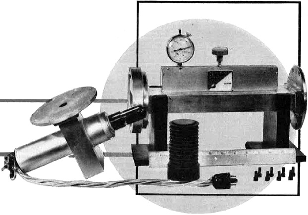
Fig. 1 - A 6V6 tube mounted in a wave guide and cavity system
for generating microwaves with a conventional receiving tube.
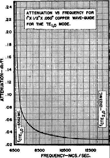
Fig. 2 - Graph of attenuation vs frequency for a 1 x 1/2
inch wave guide suitable for 10,000 to 10,500 mc. ham band operation.
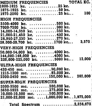
Table 1 - Currently authorized ham bands.
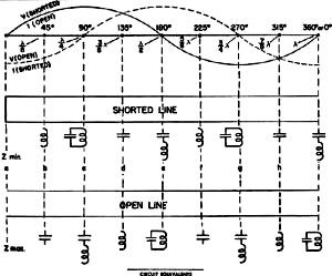
Fig. 3 - How coils and condensers, alone or as series or
parallel circuits, can be eliminated by moving along a quarter wavelength within
any over-all half wavelength.
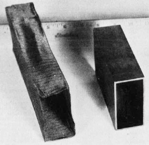
Fig. 4 - Commercial vs homemade wave guide for the 3300-3500
mc. band. This 3" x 1 1/2" wave guide has a power handling capacity of nearly 3,200,000
walls.
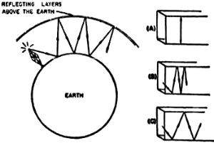
Fig. 5 - Nature's wave guide on low frequencies vs fabricated
wave guides on microwaves. Wave guide is shown at cut-off, above cut-off, and at
even higher values.
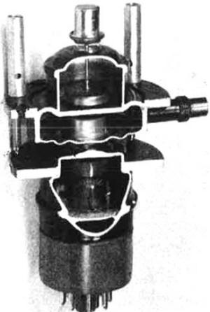
Fig. 6 - Cutaway view of reflex klystron. The negatively
,biased repeller atop the tube turns the electrons back to the positively biased
grids. A cavity circuit is set up between pairs of grids. A tube of similar type
can be used at 3300-3500 mc.
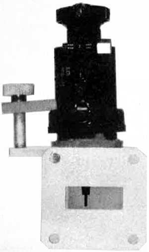
Fig. 7 - A reflex klystron tube with its output coupled
into a wave guide as required for operation in the 10,000 to 10.,00 megacycle ham
band.

Fig. 8 - Circuit of one-tube microwave receiver using conventional-type
tube.
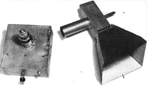
Fig. 9 - One-tube microwave receiver using single 6F8G tube.
The horn unit comprises the antenna and transmission line when placed over the tube.
The growing problem of TVI will eventually force hams to "move upstairs" into
the microwave bands.
Since May 1945 the Federal Communications Commission has reserved seven bands
of microwave frequencies for the exclusive use of hams. Ideally located between
420 and 22,000 mc., this allocation provides over 2,000,000 kilocycles of spectrum
as compared to the 16,000 kilocycles now used for approximately 99 percent of all
ham transmissions.
It is now seven years since these bands were assigned to the hams yet, with the
exception of the 420-450 mc. band, activity in these bands is negligible. This state
of affairs is inconsistent with the ham's traditional role as a "radio pioneer."
The fact that 15,000,000 television receivers are now in the hands of the public
with more to come as new stations bring larger areas of the country within the fold
will provide a powerful impetus in "kicking the amateurs upstairs." If there is
to be any lasting peace and harmony between the millions of televiewers and the
thousands of amateurs, the only real solution lies in a voluntary, or perhaps involuntary,
exodus of radio hams to the high frequency, or microwave, side of the television
frequency bands.
Ham transmissions on the present popular amateur bands will continue to cause
interference in nearby receivers with the attendant protests from irate TV fans.
Although it is technically and theoretically possible to eliminate such interference,
it is sometimes financially unfeasible to do so. The mere fact that one amateur
station can operate in a certain area without causing interference in nearby television
receivers is no guarantee that the equipment will continue free from TVI. All the
ham has to do is change frequencies or equipment or for a neighbor to buy a different
type of TV receiver and the problem of interference becomes critical.
The public's investment in television receivers now aggregates three billion
dollars as compared to the approximately thirty million dollars which hams have
tied up in their equipment. Thus the hams' stake in radio gear has been exceeded
a hundredfold by the public's investment in home receivers. In terms of the number
of households affected (or in votes at election time), the relationship is even
more top-heavy. At the present time there are over 200 times more television households
than there are ham radio homes. Even the ham often finds himself in the unenviable
position of having his ham equipment interfere with his own television reception!
A showdown is in the making at the present time and eventually the ham will wind
up in the microwave region and, in the opinion of the author, when this happens
it will be the greatest "blessing in disguise" ever vouchsafed the radio art.
The situation is even more critical than it was in 1922 when radio broadcasting
developed virtually overnight into a hydra-headed monster of gigantic proportions.
At that time, amateur radio had to move up in the radio spectrum and operate on
the high frequency side of radio broadcasting. This enforced move made the ham's
equipment and techniques obsolete and unsuitable. Specifically he had to discontinue
operations on frequencies of 1500 kc. and lower where he had employed a spark coil
or rotary spark transmitter, crystal receivers, monstrous an-tennas, and wireless
telegraphy. He was forced to operate in the band from 1500 kc. upward with equipment
requiring the use of vacuum tubes and careful attention to impedance matching.
In a matter of months this enforced move resulted in several important developments.
The move led to the discovery of the Kennelly-Heaviside layer, reliable determination
of sky wave skip phenomena, and the establishment of the advantages of short-wave
operation.
The ham was delighted to discover that with a fraction of the power needed on
the lower frequencies he could communicate world-wide - even to the antipodes. Even
a small receiving tube, such as the now-obsolete UV201A, was sufficient to serve
as a transmitter to reach all the way to Australia. The range of communication jumped
from the usual hundred miles or less to distances circling the globe. Furthermore
the ham could make his contacts by voice or radio-telephony instead of code or radio-telegraphy.
Today a similar situation exists except that now the amateur will move to a much
higher and more spacious spectrum. He can achieve efficiencies in circuitry never
before possible since he can dispense with lumped or specially-provided inductances,
condensers, and even resistors with their losses. He can develop and control the
electric and magnetic fields through distributed inductance, capacitance, and impedance
by means of the physical arrangement of simple metallic shapes.
On microwaves, the amateur will again be recognized as one of the nation's most
valuable sources of original research and experimentation instead of a mere nuisance
as he has now become in the opinion of millions of televiewers. On microwaves, where
amateur radio now more properly belongs, hams by their very number and geographical
distribution will open a new era in amateur radio. They will quickly overtake the
billions of dollars' worth of professional microwave development that has thus far
taken place without his participation. He can ultimately save the taxpayers untold
sums which are now going into microwave research and development. In the past decade
it has been demonstrated that professional microwave activities have been unable
to keep microwaves simple and inexpensive enough to encourage their widespread usage.
Only the radio amateur is in a position to substitute empirical (cut-and-try) methods
for the calculated complex and planned procedures of government and industry. There
are relevant discoveries yet to be made which can best be made by a free exchange
of information and experiences by amateurs operating largely "without rhyme or reason"
techniques.
The radio amateur today has a large number of frequencies in which he is free
to operate. These frequency bands are listed in Table 1.
It is estimated that most of the licensed amateur radio activity in the United
States is concentrated in the high frequency band, representing a total of only
3570 kc. out of the total 2,256,670 kc. assigned to hams. They, plus the bulk of
the rest of the hams operating on the 50-54 mc. and 144-148 mc. bands, are the source
of the TVI. The hams have congregated into 11,670 kc. of the amateur spectrum subject
to TVI while doing little to equip themselves and engage in operations on the balance
of the 2,245,000 kc. assigned to them. They are jammed into less than one-half of
one percent of the spectrum and are ignoring the more than 99% percent of the spectrum
in which TVI would be virtually nonexistent.
Microwaves have been generally recognized to be the frequencies between 300 and
3000 mc. (known as ultra-high frequencies) and between 3000 and 30,000 mc. (known
as super-high frequencies). The FCC has allocated 9.8 percent of all ultra-high
frequencies and over 7.3 percent of all super-high frequencies for the exclusive
use of hams. On a non-exclusive basis, the amateurs may also use all frequencies
above 30,000,000 kc. on to infinity or cosmic rays, including the bands known as
"infrared," "light," "ultra-violet," "x-rays," "gamma rays," and beyond.
Microwave Techniques
Basically, the difference between microwave operation and transmissions at the
lower frequencies is a matter of equipment. In the case of microwave operation there
is no need for specially-provided transformers, coils, condensers, or resistors.
As shown in Fig. 3, all of these components are replaced by positions taken
along a closed or shorted pipe (called a wave guide). In practice. this pipe is
usually rectangular with its wide dimension exceeding a half wavelength. Fig. 4
is a photograph of a commercially-available model and an improvised unit made of
screen wire. The home-built unit can be made out of foil or any other conductive
or non-conductive material as long as the inner surface is a good conductor. If
a simple can is used instead of a pipe, the unit is called a "cavity." Only the
frequencies which have electric and magnetic field distributions that fit inside
of such a can or cavity will exist in same. Thus, it is a frequency controlling
element hat replaces quartz crystals on the lower frequencies. For the amateur frequencies,
the cavities can have a "Q" on the order of 10,000 or more.
On the frequencies that the radio amateur best understands (frequencies below
450 mc.) , he has been conveying energy by means of conductors such as circuit wiring.
On the microwave frequencies, he conveys the current by means of electric and magnetic
field displacements within the wave guide. In other words, microwaves are characterized
by the displacement technique while conventional frequencies use conduction or the
cumbersome electric power line technique.
On microwaves, the phenomenon of space radio propagation is extended to the passage
of energy within the equipment itself and the transmission line system. The method
by which this takes place is shown in Fig. 5. One side of the wave guide pipe
(Fig. 4) simulates the ionosphere while the opposite side simulates the earth.
Fig. 5 shows a several-hundred-foot medium frequency broadcasting tower used
for sky wave transmissions by reflections between the ionosphere and the earth.
Fig. 5A shows a rectangular pipe (artificial or fabricated wave guide) which
replaces "Nature's wave guide" and performs the same function. In Fig. 5A the
pipe is less than a half wavelength or at cut-off. Energy will not proceed down
the pipe and attenuation is maximum. Fig. 5B shows what happens if the wave
guide is wider than a half wavelength. Energy will propagate down the wave guide.
Fig. 5C shows what happens if the wave guide is made even wider. Energy will
be propagated even better with less attenuation or losses. In order to keep this
explanation simple it is desirable that the dimension of the guide not approach
or exceed a full wavelength. If the guide is wider than a full wavelength, the energy
divides itself and becomes similar to two wave guide pipes. Two energy patterns
or modes would then exist side by side. In addition, the narrow side of the rectangular
wave guide would accommodate a pattern. The narrow side walls function to keep the
other two walls properly spaced. They also determine how much power can be handled
by the wave guide. The wave guide of Fig. 4 can handle up to 3,200,000 watts
of power without breakdown or flashover. Fig. 2 is a graph of the performance
of a wave guide suitable for the 10,000 to 10,500 mc. amateur microwave band. The
rectangular pipe has an inside dimension of .9" x .4". Part A in Fig. 5 corresponds
to 6562 mc. on the graph of Fig. 2. Part B in Fig. 15 might correspond
to 7500 mc. on the graph of Fig. 2. Part C might correspond to 10,500 mc. on
the graph of Fig. 2. At 13,123 mc., two modes of energy will form, changing
this particular energy designation from "cut-off frequency of transverse electric
mode 1,0" to "cut-off frequency of transverse electric mode 2,0."
It is preferable to operate in the dominant or first mode for reasons of simplicity.
It is feasible, and research has been conducted along these lines, to use several
modes, each a separate channel of communication. If the wave guide is two wavelengths
in width, there would be four modes of energy. If it is three and one-half wavelengths
in width, there would be seven modes of energy, etc. Fig. 2 also shows the
attenuation in decibels-per-foot for a particular size wave guide. In this case,
in the 10,000 mc. amateur microwave band, it is less than .035 db-per-foot. The
wave guide could be over 28 feet long before the energy would be attenuated 50 percent.
By selecting an appropriate size wave guide, minimum attenuation can be obtained
for any frequency. This same concept holds true even on low frequencies except that
at 4000 kc., for example, the wave guide pipe would have to be substantially greater
than a half wavelength, or 123 feet in width. It is only because of the shorter
wavelengths which make possible convenient physical dimensions that it is possible
to take advantage of microwave techniques that would be impossible or unfeasible
to employ on lower frequencies. The technique would otherwise function on any wavelength
as long as physical dimensions and associated costs are not prohibitive. The amount
of power which such a wave guide can handle depends upon the height of the guide.
For the wave guide of Fig. 2, the power handling capacity is 235,000 watts.
The smallest size wave guide, such as the one required for 21,000 to 22,000 mc.,
will still exceed 60,000 watts power handling capacity. Since communication at microwave
frequencies can be carried on with a fraction of a watt power (even microwatts)
there need be no concern that the user might, in any way, exceed the power handling
capacity of a wave guide.
To further appreciate wave guide phenomena, one need but recall what happens
to an auto radio receiver when the car is driven through an underpass. The underpass
is, in reality, a wave guide. Since the broadcast might be 1000 kc. (300 meter wavelength),
such an aperture or wave guide would have to exceed 500 feet in diameter in order
for the signals to go through. Police radios and two-way vehicular systems have
no difficulty in communicating in such a wave guide since their operating wavelength
is substantially shorter and will fit inside such boundaries. The wavelengths involved
for the amateur microwave bands range from as little as a half inch on 22,000 mc.
to as much as 14 inches on 1200 mc.
There are many other methods of handling microwave energy of which the "G string"
and the "helical coil" are particularly interesting examples. In the case of the
helical coil, the coaxial inner conductor connection is extended into a coil which
serves as a wave guide. With the "G string," the coaxial connector inner connection
extends as a straight wire while the coaxial connector outer connection flares out
into a horn which focuses the energy onto this straight wire.
Tubes for Producing Microwaves
There are several tube types or tube techniques for generating microwaves. Where
one can be purchased at surplus, a reflex klystron is a useful means of generating
microwave frequencies. Fig. 6 is a cross-section view of a type which is approximately
correct for the 3300-3500 mc. amateur band. It has a cathode, a pair of grids, and
a repeller. A repeller is equivalent to a plate but is biased negatively instead
of positively. The grids operate at a high positive potential. A cavity connects
to the grid extremities to form a tuned circuit. If modulation or audio is impressed
on the repeller voltage, the tube will serve as an FM transmitter.
Fig. 7 shows how a reflex klystron tube is coupled to the wave guide. The
output electrode extends into the wave guide as if it were a quarter-wave grounded
antenna, in low frequency applications. Energy then propagates down the wave guide.
An adjusting screw tunes the cavity contained within the tube itself. Such a tube
and wave guide is nearly correct for the 10,000 to 10,500 mc. amateur microwave
band.
Fig. 1 shows a conventional tube enclosed within a wave guide cavity. In
this application only the tube frequencies which can exist for that size microwave
plumbing are available and utilizable. The grid and plate leads can be adjusted
external to the guide. The photograph also shows an elaborate wave guide attenuator
consisting of a carbon-coated resistor that can be inserted into or withdrawn from
the wave guide. A gauge is used to indicate how much attenuation is being inserted.
Other means of providing microwave energy include:
1. Tubes having very close inter-electrode spacings while maintaining low orders
of interelectrode capacitance by their geometrical design.
2. By using conventional tubes with the transit time between cathode and plate
equal to more than a period of oscillation in order to maintain proper phase relations
even though the transit time is too long with respect to the same period or cycle
of oscillation. It can be corrected for a subsequent period. The electron transit
time may take two or more periods of time to reach the plate from the cathode but
it must arrive at the plate during the correct part of the period. This is accomplished
by means of suitable voltages.
3. By use of a spark gap within a shielded wave guide. A spark gap generates
the frequency spectrum while the wave guide plumbing enclosing or connected to it
permits only the microwaves to propagate.
In its simplest form, a microwave transmitter is merely a signal source which
may be a tube or a spark gap and a wave guide pipe. The outer end of the pipe will
squirt energy into space from the end of such a wave guide. If a horn extends from
that end, the energy may be concentrated or directed as desired. The beam may be
sharpened or broadened by changing the length and angle of the flared horn.
The simplest microwave receiver is a silicon or other type of receiving crystal
connected to a pair of headphones. A more elaborate receiver may consist of a crystal
detector followed by several stages of audio or video amplification. Still more
elaborate is a crystal mixer stage in which the crystal output is mixed with a local
oscillator (which may be the transmitting tube) to yield an i.f. frequency which
is then handled by a superheterodyne circuit similar to the one used on the lower
frequencies.
Fig. 8 is the schematic of a one-tube microwave receiver used by the author
in his laboratory experiments. The same tube serves as a combination r.f. amplifier,
detector, first audio amplifier, as well as providing for possible a.v.c. connections.
Fig. 9 shows how this receiver appears, complete with its antenna system made
of brass foil. The horn and wave guide section slips over the tube with a coaxial
tuning plunger connecting to the grid of the first half of the Type 6F8G tube. The
antenna system comprises an electromagnetic horn, tapering to a round wave guide.
The coaxial plunger, consisting of a movable short, permits adjustment of the wave
guide system.
Propagating Characteristics
The statement or belief that microwaves can only be used within the unobstructed
horizon is completely erroneous. Such ideas were also prevalent before the amateurs
opened up the short-wave band in 1922 and when "five-meter" radio opened up in 1932.
Skepticism was rampant when police two-way radio began expanding on v.h.f. around
1935 and when radar on microwaves moved up into the 200 mc. region and above in
1940-41. In every case, equipment has operated beyond the horizon, with many instances
having been recorded showing transmissions of several thousands of miles. Once this
fact was established, our research experts were able to layout study programs for
yielding an explanation as to how this could occur. New and relevant factors became
known. On short-waves, it was the Kennelly-Heaviside layer, first believed to be
a single layer and later found to consist of several layers - each of which was
responsible for a new set of radio communications ranges. On very-high frequencies,
it was the dispersion effect at the horizon plus natural wave guide paths resulting
from walls of buildings, sides of hills or mountains, walls of a canyon, or boundaries
set by wayside wires and fences, etc.
On microwaves, the possible range of operations is unlimited if the following
conditions affecting propagation through space are recognized.
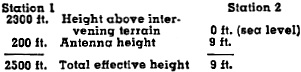 1. Direct path communication within the unobstructed
horizon. This is approximately equal (in miles) to 1.41 times the square root of
the antenna height (in feet) above the intervening terrain plus the same conditions
for the second station. For example: 1. Direct path communication within the unobstructed
horizon. This is approximately equal (in miles) to 1.41 times the square root of
the antenna height (in feet) above the intervening terrain plus the same conditions
for the second station. For example:
Station 1 has a radio horizon of 1.41 * √2500 = 1.41 * 50 or 70.5 miles
while Station 2 has a radio horizon of 1.41 * √9 = 1.41 * 3 or 4.23 miles.
The two stations can thus intercommunicate over a distance of 74.73 miles by direct
path.
2. Indirect path or reflected communication. This type of transmission may exist
either within the horizon, beyond the horizon, or by a reflection within the horizon
passing the energy on to another reflecting or pickup point beyond the horizon of
the originating station. To understand how "this happens, one should consider the
source signal as a beam of light and every solid object encountered enroute as a
reflecting mirror. Whatever a mirror of such shape would do to light, a similar
thing will happen with respect to microwaves. Reflections will be more effective
when obstructions enroute are substantially larger than the wavelength. This is
quite likely to happen since microwaves are normally less than one foot long. Even
dense cloud formations have reflective possibilities. At their greatest height,
they can develop great ranges, even for stations operating at sea level with very
small unobstructed horizon.
3. Wave guide paths. Microwave energy may recognize the space between two wires
as the equivalent of the two walls of a wave guide pipe. It will treat one wire
as if it were the ionosphere, and the other the earth, and try to propagate skywave
fashion between such boundaries. The limit of such a communications range is the
limit of the availability and existence of suitable wire arrangements around the
country. Even the space between railroad tracks can serve as a wave guide, as can
tunnels, underpasses, canyons, gorges, etc.
4. Atmospheric ducts. These are a function of weather and can make microwaves
a tremendously valuable tool in weather forecasting. Microwave propagation at great
distances can be tied in with weather conditions. Microwave energy recognizes the
boundaries of a stratification of temperature or pressure aloft as a wave guide.
It also considers the adjacent boundaries of two strata a wave guide. If signal
energy from a transmitter can enter one of these atmospheric ducts or wave guides,
the range of communication can become very great - often up to thousands of miles.
This fact has been verified on many occasions and is undergoing continuing research
by governmental and subsidized institutions. In investigations of this type the
hams will be invaluable because of their large groups, geographical distribution,
and the number of hours they spend on the air. The phenomenon is often missed by
the professional groups working the modern 40·hour week.
Although thousands of persons are currently employed in the microwave industry
involving the expenditure of billions of dollars, very few of these persons and
only a small portion of the total funds are actually used for propagation studies.
Instead, most of the time and money has gone into the design and construction of
complex and expensive radar and microwave relay systems.
The author feels confident that when the hams really get into microwaves in sufficient
number, the "CQ" call will yield just as interesting responses as those enjoyed
now. Microwaves also offer infinite possibilities for a ham organization like the
ARRL to live up to its name. Microwaves are an excellent medium for radio relaying
and for working out communications networks with a wide selection of echelons to
communicate during emergencies and civil defense operations.
To utilize the microwave frequencies, the radio ham has to become more of a mechanic
than an electrician. He must get used to pipes called wave guides and metallic structures
having certain shapes, configurations, and dimensions. He will use "cut-and-try"
methods and simple arithmetic in his computations. He will be required to perform
simple sheet metal and machining operations in building his apparatus but will probably
purchase certain of his gear such as the wave guide probes and coaxial connectors,
if they are readily available, otherwise he will build or improvise them from whatever
is at hand. There is not one single thing connected with microwave operation on
the ham bands that cannot be built or improvised very cheaply if the ham is willing
to experiment. Microwaves offer a real challenge to the alert ham-a challenge very
few hams will be able to resist!
Posted May 1, 2023
(updated from original post
on 5/27/2013)
|