|
Once frequency modulation (FM)
began making inroads in the commercial radio broadcast world, it wasn't long until
the pundits were writing eulogies for amplitude modulation (AM). There was/is no
denying the superiority of FM in terms of both natural (QRN;
e.g., lightning, static, arcing contacts) and manmade (QRM;
e.g., another radio, Wi-Fi, cellular) interference, but there was already a large
installed base of AM radio receivers (and broadcast transmitters) that satisfied
their owners' expectations for listening to news, ball games, music, and the well-established
repertoire of drama and comedy shows. FM radios were generally more expensive to
manufacture, operate, and repair than AM - at least early on, especially since typically
FM sets included AM as well. This particular article from a 1944 issue of Radio
News magazine discusses
class C
amplifiers, which is a mode of operation where the circuit is conducting for less
than 180° (half a cycle) when a sinewave is applied. When properly implemented,
class C operation is more efficient than
class A
(360° conduction) or
class B
(180° conduction), or
class AB
(180° to <360° conduction). The principles are the same whether vacuum tubes
or transistors are used.
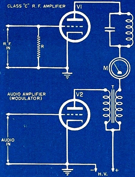
Modulating Class "C" Amplifiers

Fig. 1 - Diagram showing method of plate modulating a class "C"
r.f. amplifier.
By M. Dean Post, Senior Instructor, AAFTTC
Important factors to be considered when employing amplitude modulation in class
"C" plate modulated r.f. amplifiers.
Enthusiasm for frequency modulation is sweeping the nation, but amplitude modulation
has not yet outlived its usefulness. It is, in fact, still the most common method
of inserting intelligence into a carrier wave. From some of the questions asked
by radio men, it is apparent that the subject is none too thoroughly understood
even at this late date, and so long as such modulation is used, it deserves as much
understanding as possible. There are some excellent texts on this type of modulation,
but it is intended here to present some succinct facts without digressing too much
into the realms of abstract theory.
There are several means of amplitude modulating a class "C" amplifier among them
being plate modulation, grid modulation, cathode modulation, and combinations of
all three. The first type will be used here for purposes of discussion, since all
types accomplish essentially the same thing. Fig. 1 shows a typical schematic diagram,
simplified for explanation.
The r.f. class "C" amplifier is so designed that the r.f. driving voltage appearing
across the grid resistor R is rectified by grid-cathode current flow and causes
a large d.c. voltage to appear between grid and ground, negative at the grid end.
The amplitude of this potential is such that the amplifier is biased from two to
four times cutoff. The audio signal is amplified by the modulator tube V2, and this
signal appears across the secondary of the modulation transformer T. Conditions
now have been set up for modulation.
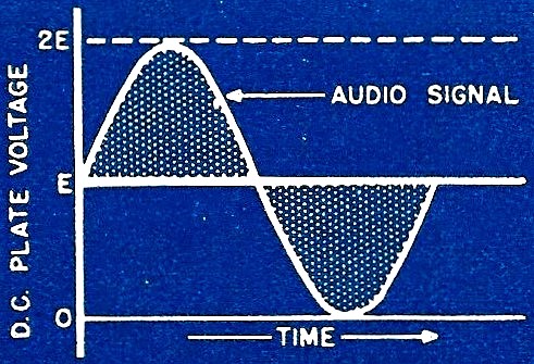
The audio signal has been inserted in series with the d.c. high voltage supplying
the plate of the r.f. amplifier, so that it will alternately add and subtract from
the total voltage appearing on the plate of V1, as shown in Fig. 2. It is apparent
that, if the audio signal is of sufficient amplitude, it can be made to raise the
total plate voltage to twice its normal value, and lower it to zero. This condition
will result in 100% modulation of the carrier wave. Thus, an important requirement
has been revealed: the peak output voltage across the secondary of T (Fig. 1) must
equal the d.c. voltage applied to V1 if 100% modulation is to be realized.
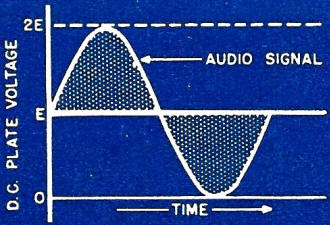
Fig. 2 - Audio signal, which is inserted in the plate of the
r.f. amplifier tube.
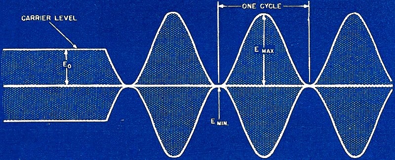
The result of such efforts is to vary the carrier output in the manner of Fig.
3. For ease of drawing, this figure is a graph of the envelope of modulation, and
does not include the individual cycles of r.f. energy that make up the body of the
envelope. This curve is that of either current or voltage - not power - and is the
one shown on the face of a cathode-ray oscilloscope when r.f. energy is applied
to the vertical plates. The percentage modulation can be obtained from the expression
where the voltages are as shown in Fig. 3. (It should be noted that the envelope
above and below the zero axis is symmetrical and sinusoidal, since a sine wave was
used initially as the audio signal. Thus, for detection purposes it is only necessary
to remove the lower half of the envelope to obtain the original signal.)
The envelope of Fig. 3, however, does not tell the entire story. There remains,
among other things, the problem of determining how much power is required to accomplish
100% modulation, and what happens to the radiated power.
The above envelope follows the curve
E = E0 (1 + m·sin ωt)
........................ (1)
where m is the modulation factor (1 for 100%). This expression simply states
that the carrier E0 is being modulated by a sine wave. Now, If it is
remembered that power is proportional to the square of voltage, it can be stated
that
E2 = E02
(1 + m·sin ωt)2
= E02
(1 + 2m·sin ωt + m2·sin2ωt). (2)
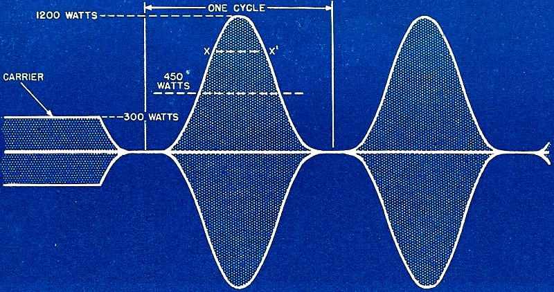
If equation (2) is plotted over one cycle, the envelope of modulated power will
be obtained as in Fig. 4. This curve seldom is seen in plotted form, since the voltage
envelope is more readily adaptable to percentage-modulation measurements. However,
Fig. 4 gives a clearer picture of the power relations than otherwise can be obtained,
and serves to illustrate actual operating conditions. For convenience in calculating,
values have been assigned-a carrier power of 300 watts being taken for a basis.
The curve of Fig. 4 is striking in its dissimilarity to the voltage envelope
of Fig. 3. Note the wide space of practically no power between cycles. This vacancy
is caused by two things:
1. The negative voltage peaks of modulation have reduced
the r.f. peak power greatly.
2. The time that each cycle of r.f. power flows has been
narrowed, since the pulses of r.f. energy are very narrow at their tips.

Fig. 3 - Voltage envelope of the r.f. carrier when 100 percent
modulated.
The cumulation of these two items results in the extreme necking out of the envelope.
The strangeness of the remainder of the curve is accounted for by referring back
to equation (2), which tells us that there are three components present: the steady
carrier, the modulating signal, and a double-frequency component which is represented
by the sin2ωt portion. Apparently the process of modulation has
added something new to the carrier-sidebands.
These sidebands are composed of sum and difference frequencies (carrier plus
audio, carrier minus audio) and convey all the intelligence of the modulation. Thus,
the carrier is truly named, since it contributes nothing towards the information
contained in the wave. The carrier could be removed without loss to the intelligence
conveyed, and in some types of transmission this is done.
It is interesting, at this point, to determine how the total power has been altered
by modulation. Fig. 4 shows that the peak power is four times the unmodulated power-and
this we would have known previously, since the plate voltage was doubled and this
means in itself four times the power. If the total area (power) under the curve
is compared with the total area enclosed by a full cycle of unmodulated carrier,
it will be apparent immediately that the total energy has increased by half. Thus
the total modulated power is 1.5 times the unmodulated power. Now, if the total
modulated energy is 1/2 greater than the unmodulated power, the additional energy
must have been supplied by the modulator. Again an important item comes into view-for
100% modulation, the audio system must be capable of supplying a power which is
half the r.f. power. Furthermore, all the modulator supplies is sidebands.
The expression for the entire waveform of the modulated r.f. voltage is
 (3) (3)
This slightly formidable-appearing expression is really quite simple. It consists
of the carrier power (sin ωct), the lower sideband which has a
maxi-mum amplitude of m/2 and is composed of the carrier frequency We minus the
signal frequency ωs and an upper sideband with the same maximum amplitude
but whose position in frequency is the sum of ωc and ωs. The
equation says that the amplitude of the sidebands is 1/2 that. If the carrier when
m = 1. Since power is proportional to the square of the amplitude, the sideband
power is 1/4 plus 1/4, or a total of 1/2 that of the over-all power. It has been
shown already that the total power increase at 100% modulation is 1/2; therefore
the two sidebands must contribute the extra 1/2. Thus the ratio
This proves that the sideband power is 33 1/3%; therefore, the carrier must contribute
the remaining 66 2/3% of the energy.
From equation (2), it is apparent that the maximum power of the side-bands is
proportional to m2. It is thus important to keep the modulation as high
as possible, since the total energy in these sidebands will decrease rapidly as
the percentage modulation is reduced. For example, if the modulation were reduced
from 100% to 80%, the intelligence-bearing sideband power would be reduced to 64%
of its former value. This clearly shows that a high-power carrier poorly modulated
would be no louder at the receiver than a weak carrier fully modulated.
Fig. 4 is somewhat puzzling at first glance in that the carrier has been engulfed
entirely in the total energy under the envelope, and is no longer distinguishable.
As a matter of fact, it is impossible to state from such a curve that the carrier
is actively engaged in producing 66 2/3% of the total energy. This conclusion must
be drawn from knowledge of the sideband situation: if the sidebands supplied by
the modulator are accounting for 33 1/3% of the total energy, the carrier must therefore
be supplying the remainder.
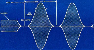
Fig. 4 - Power envelope of the r.f. carrier when 100 percent
modulated.
The dotted line marked 450 watts in Fig. 4 represents the power to which the
carrier would have to be raised if the continuous unmodulated power were to equal
the 300-watt carrier fully modulated, and is the average value of energy over one
cycle of modulation. It thus is evident that the class "C" amplifier, under modulation,
is subjected to heavier loads. If the r.f. tube is to be modulated 100 %, it must
be operated at lower plate voltages than at telegraph or unmodulated conditions
since the plate dissipation is increased. The tube must be capable of handling twice
the peak modulating voltage - otherwise, tube saturation will be reached and exceeded,
causing over-heating and overmodulation.
This brings up other items - those of downward modulation and overmodulation.
When the class "C" amplifier is 100% modulated, the average d.c. current, as indicated
by the meter M in Fig. 1, will not change its reading, or will just barely flicker
upwards. This can be seen from Fig. 2; when the peak modulating signal is just equal
to the d.c. voltage applied to the r.f. amplifier plate, the average increase (over
one cycle) of voltage is zero. Therefore the average d.c. current flow produced
will be independent of modulation. If the modulating signal is too large, it will
drive heavily in the positive direction, and be cut off at the negative portion,
thereby increasing the over-all d.c. voltage and causing more d.c. current to flow.
This results in cutting off the modulated power for excessive periods between cycles,
which causes distortion and the production of spurious sidebands. Many operators
have operated their transmitters with considerable increase in d.c. plate current
on modulation, thinking they were just "hitting it harder." They were - but with
negative results. When a lamp load was coupled to the output coil, they were surprised
to see the power decrease on modulation. As has just been mentioned, too heavy modulating
signals will cut off the power between cycles, the amount depending on the extent
of overmodulation. Thus the average power is reduced, even though the d.c. plate
current has increased; and downward modulation results. In this case, downward modulation
is the result of overmodulation.
It is interesting to note from Fig. 4 that the audio modulator must supply peak
power of four times its normal power - which would possibly lead one to conclude,
offhand, that the audio system must be larger than previously thought. Further investigation
will clear up the matter. The points X and X' are the half-power points of the curve
- the points at which power has 0.707 of its maximum value. (This is a standard
investigation point.) The time of power flow between these two points is 90°,
or 1/4, of a complete cycle. Thus, the audio system must supply its normal power
for one cycle, or 4 times that power for 1/4, cycle - identical conditions. However,
this power is required only for sine wave conditions. The power requirements for
speech are generally less, because of the narrow wave forms inherent in speech.
The peak requirements remain the same, but the average audio power is reduced to
some 30% of the carrier instead of 50%.
A method of approximating the percentage modulation is to observe the current
rise in the antenna or feeder circuit, on modulation. If the total power at 100%
modulation is 1.5 times the unmodulated carrier power, then
P = I2R and
1.5 = I2
(since R remains constant it can be considered as 1)
Therefore I = 1.225, or the current has increased 22.5% for 100% sinewave modulation.
Linearity is important in modulation, and is dependent on the grid bias and load
impedance. A high load impedance. as computed by Z = E/I, where E is the d.c. plate
voltage on the r.f. tube and I is the d.c. plate current, gives more linearity but
lower output, and vice versa. Care must be taken in the selection of r.f. tubes,
and in the grid bias. If reasonable power output with low minimum plate voltage
is required, a tube with a low amplification factor is necessary. The driving power
required for good linearity increases rapidly as 100% modulation is approached,
hence the driving source of r.f. power exciting the r.f. amplifier must have good
regulation.
Posted January 11, 2024
(updated from original
post on 11/26/2019)
|