|
Reading this
article from a 1950 issue of Radio & Television News magazine reminds me of a
basic truth - at least for receiving, it is usually possible to realize obtain
useful operation with just about any reasonable length of straight wire for an
antenna. Transmitting is a different story since poor VSWR conditions on the
antenna connection can damage or cause to shut down the output stage of an RF
power amplifier. Still, if your transmitter can survive a high VSWR, then
chances are you can send out a useful signal. You won't be breaking any DX
records or winning any contests, but you won't be
dead in the water. Surely anyone over 40 years old has
jury-rigged an FM radio antenna out of a length of straight (or bent) wire and/or fashioned a
sheet of aluminum foil around a set-top television antenna to pick up an
acceptable signal. In many cases where the 300 Ω twin-lead cable was
improperly snaked along an aluminum gutter or aluminum siding on a house on its
way to the rooftop antenna or had a long length of excess cable coiled up on the
roof or behind the TV set, the horrendously mismatched connection caused the
cable to serve more as the actual antenna rather than the one on the roof.
A Two-Band Piece of Wire
 By Karl Dreher, W0WO By Karl Dreher, W0WO
An easy-to-build, economical, highly efficient, multi-band antenna for the amateur.
In this era of multi-element rotary beams, stacked arrays, squashed cubicle quads,
and other catch-named antennas, it may be reassuring to realize anew that a single-wire
antenna properly connected to a receiver or transmitter still works well. The degree
of its performance depends greatly upon how efficiently it is connected. Being a
more than one-band operator, the author some months ago dreamed and figured at considerable
length on just how to feed a long, high-wire antenna so that it could be used on
two or more harmonically-related bands, using a flat or untuned feed line, and still
maintain efficient matching of feed line to both antenna and transmitter or receiver.
One cold, early dawn the subconscious mind awakened the outer man, and several curves
were hastily drawn, resulting in a very simple yet conclusive answer to how the
problem could easily be resolved.
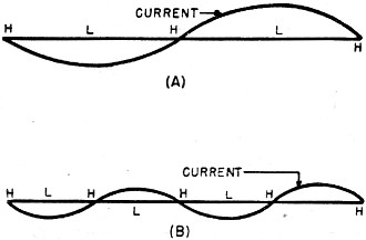
Fig. 1 - Wavelengths on a wire.
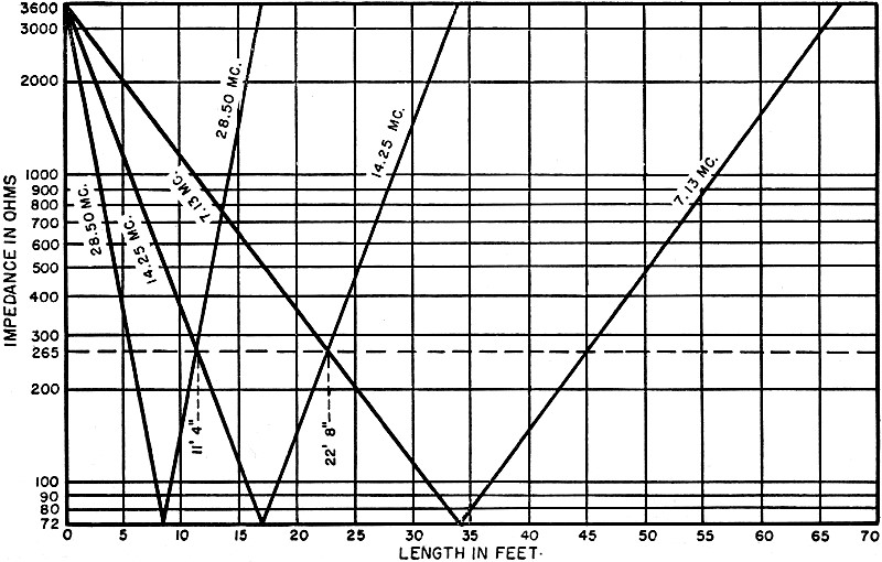
Fig. 2 - Chart of inductive reactance of long wire.
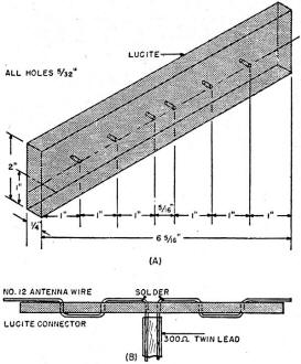
Fig. 3 - Method of lacing wire through connector and attaching 300 ohm line.
Perhaps at your amateur station location, you have some means of supporting in
the clear a single piece of wire 68 feet long and would be interested in erecting
in this available space a highly-efficient yet very simple antenna at but little
cost. Or maybe you are starting from scratch and desire an effective sky-wire whose
erection requires very little technical and structural knowhow and one that is inexpensive
to build. If you fall in either of these categories or simply would like to try
something a little different in the way of an antenna, then the one described herein
should interest you.
Theory
A piece of wire 68 feet long and in the clear will resonate at approximately
two half-wavelengths on 14.25 mc. and four half-wavelengths on 28.50 mc., according
to the accepted antenna formula. The characteristic cloverleaf horizontal pattern
of radiation makes such a piece of wire desirable as a general coverage radiator.
If such an antenna were fed with a non-resonant line, and no electrical adjustments
to it or the antenna were required when tuning up or changing operating bands, then
you would have the most simple and convenient antenna conceivable.
Such an arrangement becomes a reality when thoughtful consideration is given
to well-known fundamental electrical characteristics of long-wire antennas and non-resonant
feed lines. Fig. 1A depicts the current distribution on a 68-foot piece of open
end wire operating at 14.25 mc., and Fig. 1B shows the current distribution at 28.50
mc. In any antenna a multiple of a half-wave in length, as in Figs. 1A and 1B, the
impedance of the wire reaches its lowest value at each current loop (point L) and
its highest where the current almost equals zero (point H). Theory and practice
establish the fact that at the end, or high impedance point, the value is approximately
3600 ohms, and at the center, or low impedance point, approximately 72 ohms. Fig.
2 shows the values of impedance of a resonant half-wavelength of wire plotted against
physical length. It is to be noted that the curves cross one another at a common
point which corresponds to 265 ohms impedance at a distance of 11 feet, 4 inches
from one end.
Accordingly, the conclusion is reached that a single piece of antenna wire 68
feet long can be fed 11 feet, 4 inches from one end by a 265 ohm, non-resonant feed
line and operated on both 14.25 mc. and 28.50 mc. with perfect transfer of energy
to the system. Because height above the ground and proximity of nearby objects affect
the electrical characteristics of any antenna to some degree, the common impedance
value of 265 ohms in the described system can be considered as 300 ohms for all
practical purposes, and the 11 foot, 4 inch dimension shall be considered as 11
feet, even.
Construction
On that basis, the author cut a 68-foot piece of antenna wire 11 feet from one
end and connected in series thereto a 300 ohm, twin-lead ribbon of random length,
long enough to reach the operating position in the station. To provide a structurally
and electrically sound means of making the connection of the feed line to the antenna,
a simple connector made out of Lucite was devised and used as shown in Fig. 3. The
antenna was thus assembled, hoisted in the clear about 30 feet above ground and
placed in use.
The same principle is applied if the antenna is being constructed for 7.13 mc.
and 14.25 mc. operation. For such, however, the "300 ohm common point" is to be
noted in Fig. 2 as 22 feet from one end, and the feed line must be connected accordingly.
Ten and twenty meters at 11 feet, or twenty and forty meters at 22 feet - take your
choice; it can't be both combinations with a single connection.
Upon installation of this antenna at the writer's station, it was noted that
regardless of which of the two bands the antenna was used on, the final stage of
the transmitter did not detune from minimum plate current state when the antenna
was connected to it, thus indicating an excellent impedance match throughout the
entire antenna system. In addition, the system loaded very readily as demonstrated
by the required loose coupling of the two-turn pickup loop at the final stage of
the transmitter.
With a Class B modulated phone transmitter operating at not more than 150 watts
input, no trouble has been experienced by the writer and others in working out satisfactorily
on the 7, 14, and 28 mc. bands, even during the most congested hours. Surprisingly
enough, the antenna seems to be not at all critical as to tuning anywhere within
these bands.
With the use of a non-resonant feed line as indicated and the absence of standing
waves as borne out by test, maximum efficiency in the transfer of energy from the
transmitter to the antenna is achieved, and broadcast interference is kept to a
minimum. These desirable factors alone should appeal to any amateur, new or experienced,
and make construction of this simple antenna system a next-weekend must.
The author's address is 2062 Eudora Street, Denver 7, Colorado.
Posted February 24, 2020
|