|
November 1946 Radio News
 [Table
of Contents] [Table
of Contents]
Wax nostalgic about and learn from the history of early
electronics. See articles from
Radio & Television News, published 1919-1959. All copyrights hereby
acknowledged.
|
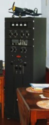 Hams like members of the Mogollon Rim Collins
Collectors Club (K0CXX)*,
play an important role in the preservation of vintage radio equipment. They own
a nice example of a Collins model 30K-5 medium power (250 W) AM transmitter
(photo at right) that is the subject of this 1946 article in Radio News.
At 5½ feet tall and weighing 350 pounds, the 30K is many times the volume
and weight of a modern solid state transmitter (transceiver + PA) having the same
capability. Its advertised price in 1946 was $1,450, which is equivalent to $19.9k
in
2022 money - obviously not in the affordability range of your
typical amateur radio enthusiast. Hams like members of the Mogollon Rim Collins
Collectors Club (K0CXX)*,
play an important role in the preservation of vintage radio equipment. They own
a nice example of a Collins model 30K-5 medium power (250 W) AM transmitter
(photo at right) that is the subject of this 1946 article in Radio News.
At 5½ feet tall and weighing 350 pounds, the 30K is many times the volume
and weight of a modern solid state transmitter (transceiver + PA) having the same
capability. Its advertised price in 1946 was $1,450, which is equivalent to $19.9k
in
2022 money - obviously not in the affordability range of your
typical amateur radio enthusiast.
* Many such websites and photos of the K30 exist, but I chose K0CXX because they
have model airplanes hanging around the building.
New Transmitter for Amateur Radio
By W. Bruene, W0TTK, and N. Hale, W0JIH
Collins Radio Company
Introducing the salient features of a new transmitter which is designed to fulfill
the needs of a large part of the medium-power ham fraternity.

Skillful design is combined with sturdy construction in this
Collins 30K transmitter.
The new Collins 30K has many features that are considered highly desirable in
amateur radio. A large number of the more than seventy-five hams in the Collins
organization had a voice in its specifications. After thorough consideration of
all their suggestions, the design engineer selected the following as the features
that could be included consistent with versatility and economy: 1. 500 watts input
on c.w., somewhat less on phone; 2. single ended output; 3. complete neutralization
on all bands; 4. low driving power; 5. band-switching; 6. v.f.o. control, highly
accurate and stable; 7. fixed bias; 8. electronic keying; 9. minimum power supplies;
10. high efficiency; 11. high level class "B" modulation; 12. speech clipper; 13.
low pass audio filter; 14. single control operation; 15. accessibility for operation
and maintenance.
The result is a versatile, thoroughly engineered transmitter with high performance
and easy operation. A more detailed description of the circuit and components follows.
1. Power input. A power input of 500 watts on c.w. and 375 watts
on phone was chosen because it is obtainable with low exciter power requirements,
moderate tube costs, and economical power supply design. The 115 volt, 60 cycle
a.c. power consumed by a transmitter of this size does not require special wiring.
2. Single ended r.f. stage. An Eimac 4-125A is used in the final
r.f. stage. This tube is admirably suited to features 1 and 2. Using one tube in
a single ended output greatly simplifies bandswitching, since only one end of each
coil is switched. The 4-125A, a notable advance in beam power tetrode development,
easily handles the desired power. Its high efficiency (75% to 80%) assures maximum
power output. The grid driving power required is well below 10 watts and can be
supplied from a low powered exciter setting on the operating desk.
3. Neutralization. The 4-125A is again suited to the purpose.
It requires no neutralization, even on 10 meters. Thus the circuit is simplified
and a clean signal is transmitted on all bands.
4. Low driving power. Discussed under the second feature.
5. Bandswitching. The 30K has bandswitching throughout, so that
the operator can change bands quickly. This is particularly desirable on the higher
frequency bands which usually are open for a limited number of hours each day. Five
separate tank coils are utilized (10 and 11 meters use the same coil), each with
its own variable link. The link couples the antenna or feeders to the cold end of
the plate coil. All links are mechanically coupled together and are operated by
a control knob on the front panel. They feed directly into 52 ohm to 73 ohm transmission
lines. For higher impedance transmission lines an external tuning circuit should
be employed. Either balanced or unbalanced antennas can be used.
6. V.f.o. control. This was accomplished with a high degree
of success. The dial is calibrated directly in frequency. The exciter unit will
be discussed in detail in the latter part of this article.
7, 8, 9. Power supplies. Economical design dictates that the
power supplies be kept to a minimum. A high voltage supply, low voltage supply,
and a bias supply provide all the d.c. power required by the 30K. A single high
voltage supply feeds both the r.f. power amplifier and the modulator tubes. Since
the 4-125A tube requires high voltage and low current, as do the 75TH modulators,
a pair of 866A rectifiers can deliver easily the required plate current for both
stages. The low voltage supply provides voltage for the 4-125A screen, the speech
amplifier, and the modulator driver. It also supplies bias voltage for the 4-125A
and the modulator tubes. With the 4-125A biased to cut-off, keying can be accomplished
in the exciter.
10. High efficiency. In the 30K circuit, plate efficiency of
the 4-125A is between 75 and 80%. The tank and coupling circuits are designed for
low loss, thus delivering maximum power to the antenna.
11, 12, 13. Speech equipment. Speech amplifiers and modulator
equipment are on one chassis located in the transmitter cabinet. The audio input
will accommodate either crystal or high impedance dynamic microphones. The amplifier
is conventional, with the exception of the speech clipper and filter employed.

Clipper circuit employed in transmitter.
Prior to the development of the 30K, a considerable amount of investigation in
the laboratories had proved the advantages of audio peak clipping. In congested
frequencies such as amateur bands, or in adverse atmospheric conditions, peak clipping
raises the effective modulation level and provides greater intelligibility at the
receiving end. It also prevents over-modulation, because audio peaks and transients
are clipped before reaching the modulator.
A low pass filter, following the speech clipper, attenuates all frequencies above
4000 c.p.s. This cut-off frequency is high enough to preserve the naturalness of
the voice, yet eliminates excessive bandwidth. In field tests, listeners have reported
that the 30K takes a comparatively narrow band width in amateur bands.
A pair of Eimac 75TH tubes are utilized as modulators. The modulation transformer
has a separate winding for modulating the 4-125A screen.
A manually operated "phone-c.w." switch is located in the modulator unit, and
is controlled by a knob on the front of the transmitter. For c.w. operation, this
switch opens the filament circuit of the modulator tubes and shorts the secondary
of the modulation transformer.
The audio gain in the speech amplifier is controlled by a knob on the front panel.
The clipping level is adjusted manually from the rear of the cabinet, and can be
set to occur at any desired percentage of modulation.
14. Single control operation. The transmitter plate switch and
the exciter switch are connected in series. Just by leaving the transmitter switch
in the "On" position, the exciter switch will have complete control of transmitting
and receiving functions. The exciter switch has an extra section for use as a receiver
disabling switch.
If push-to-talk operation is desired, the "push-to-talk" switch is connected
in series with the plate control section of the exciter switch. Both transmitter
and exciter switches are left in the "transmit" position. An extra relay is then
necessary for disabling the receiver. Calibration procedure is unchanged. Terminals
are provided for operation of a receiver disabling relay, and also for an antenna
change-over relay in the transmitter.
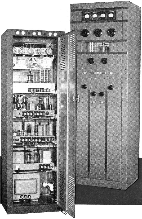
15. Accessibility. The cabinet is of sturdy welded steel construction.
All units, tubes, and wiring are easily accessible through the full length rear
door. Electrical interlocks break all high voltages when the cabinet is opened.
The door may be locked with a key to prevent entrance by unauthorized persons.
All operating controls are conveniently located on the front panel. Meters are
mounted on an insulated panel located behind a glass window near the top of the
transmitter. Another window permits observation of the 4-125A d. amplifier.
Exciter Unit
The exciter unit for the 30K can be adapted easily to drive a variety of higher
powered transmitters. All circuits are ganged together and controlled by a single
tuning knob. The variable frequency oscillator is a peacetime application of a rugged
and highly stable wartime development. The dial is calibrated directly in frequency,
and is accurate to within 1 kc. in the 40 meter band. Accuracy on the other bands
is directly proportional. The 1 kc. allowable deviation includes the frequency error
due to all normal operating conditions. The v.f.o. operates in the 160 meter band.
One control bandswitches all circuits simultaneously. The exciter covers the
80, 40, 20, 15, 11, and 10 meter bands. In the "calibrate" position, the exciter
can be tuned to zero beat with a received signal without turning on the transmitter.
Electronic keying provides fast, clean c.w. operation. When the key is removed
from the jack, the circuit is automatically closed for phone operation. The exciter
output is fed through a 73 ohm coaxial transmission line to a link on the grid coil
in the transmitter.
Operation of the exciter is extremely simple - one control switch, a bandswitch,
and single dial tuning. It can be used either as a transmitter or as a versatile
exciter. Frequency control is rapid, accurate, and reliable.
Field Tests
The 30K has been given strenuous and critical tests in actual amateur operation.
The ease and reliability of operation were firmly established. As was expected,
the speech clipper was highly satisfactory, and effectively raised the modulation
level. The signal was kept clean, and intelligibility was definitely increased.
The low-pass audio filter maintained a narrow band width. It can be said truthfully
that the clipper enabled the operator to obtain and maintain solid contacts that
would have been lost otherwise in static and crowded frequencies.
Posted July 4, 2022
(updated from original post on
11/5/2014)
|