A New Tool for the Serviceman |
|
You are taught early in your electronics
career to be mindful of the tendency for measurement equipment to affect the circuit
it is measuring, and therefore the indicated results. In the case of high frequency
circuits, even minute amounts of capacitance and/or inductance can render results
utterly unusable, but even in circuits operating down to D.C. the simple internal
resistance of a meter can profoundly affect measurement accuracy. High impedance
circuits are particularly vulnerable to such "loading" effects by test equipment.
For example, consider a circuit being measured (device under test, aka DUT) that
has an impedance of 10 kΩ and the internal resistance of the VOM is
A New Tool for the Serviceman By Joseph Heller
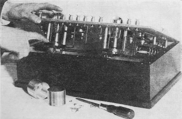
Joseph Heller, Chief Engineer of Wireless Egert Engineering, Inc., holding the vacuum tube voltmeter of his design which he describes here. This vacuum-tube voltmeter has many uses such as testing the perfection of and measuring loud-speaker reproduction and measuring the gain of any receiver circuit
In the laboratory it is often necessary to measure the voltage of a circuit which carries little current - if any - or we might want to measure a potential and not a voltage drop. The usual type of voltmeter is of course out of the question, for the same reason that the old type of voltmeter is unsuited for measuring B-eliminator voltages: i.e., the voltmeter itself draws current. When it is desired to measure voltages where no current may be drawn from the circuit, use is generally made of a vacuum-tube voltmeter. Aside from the no-current advantage of this type of voltmeter, is he added advantage that an accidental application of a high voltage will not affect the instrument or injure it in any way. The vacuum-tube voltmeter described here is equally accurate on either d.c. or a.c. and on any frequency, either audio or radio, up to 1500 kilocycles.
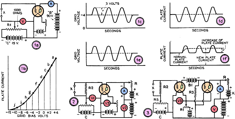
Back side of test set. Most vacuum-tube voltmeters utilize what is known as the lower bend of the grid voltage-plate current curve. The curves are obtained in a rather simple way. All that is necessary is the simple circuit shown in Fig. 1a. The tap on potentiometer R1 is turned until 4 volts of positive bias is indicated on voltmeter "V" and the reading of milliammeter "A" is noted. This reading is then plotted at some such point as "a" on the curve on Fig. 1b. R1 is then adjusted to give a slightly lower voltage reading on voltmeter "V," and again the current through milliammeter "A" is noted. This, when plotted, will give some such point as "b' on the curve in Fig. 1. Continuing in this manner we get points c, d, on the curve. At this point battery "C" is reversed and the readings continued. We will then get such points as f, g, h, etc., and draw the complete curve. Many interesting facts can be derived from this curve. Suppose, for instance, that the tube was left biased at point "g" which is equivalent to a grid bias of -4 volts. If the circuit of Fig. 1a is broken at the point "x," and an alternating current of three volts impressed across the break, then the grid voltage would appear as in Fig. 1c. The plate current would be very similar to this, as shown in Fig. 1d. Since this curve is symmetrical, its average value is shown by the dotted line. The last two curves mentioned would be alike in shape, because the magnitude of the plate current change would be practically equal whether the grid swung positively or negatively. The condition we have at this time would compare to that obtaining in a good amplifier stage. If we should, however, bias our grid to point "j" on Fig. 1b, which corresponds to about -9 volts, and again impress an alternating voltage of three volts at point "X," we will get, as a result, curves similar to those in Figs. 1e and 1f. It can be seen that the grid voltage .curve is similar to that of the first case. A marked difference is present, however, in the plate current curve. The upper half of the wave remains practically the same, but the lower half has been cut off. The voltage value shown bv the dotted line will, in this case, be displaced from the axis. We have the condition, therefore, of an alternating voltage causing an effective change in the plate current. This will make itself evident by the higher reading of the milliammeter "A." Continuing in this way it can be easily seen that, if we should further increase the grid bias negatively, there will be a change during the positive half cycle of the impressed alternating voltage. but no sensible change during the negative half; and his is exactly how the usual type of vacuum tube voltmeter operates.
In Fig. 1a is shown the circuit which is employed to obtain the characteristic curve of the tube to be used. The curve thus obtained is shown in Fig. 1b. Figs. 1c and 1d show the wave form of the grid potential and plate current, respectively, when an alternating current of 3 volts is impressed on the grid of the tube. In Figs. 1e and 1f the curves which would result, if the grid were biased to about 9 volts, are shown. Fig. 2 shows the circuit arrangement for obtaining zero reading of the instrument. Fig. 3 shows the circuit for amplifying and reading direct currents There are certain requirements which will both increase the ease of operation and the reliability of such an instrument. To begin with, a high negative bias does not mean that the plate current has been entirely cut off. While the small current which does remain would not make itself evident in a high range milliammeter, it will make itself very troublesome in the sensitive micro-ammeter generally used. The reading can be reduced to zero in the manner shown in Fig. 2. By varying rheostat "R" we can send through the meter a current from battery "K," equal and opposite to the current set up by the plate battery. The meter will read zero and any change in plate current will make itself evident by a deviation from zero. In the actual construction of this instrument, the voltmeter, V1, Fig. 2, should be included as well as a filament voltmeter V3. The fixed resistance R2 in Fig. 2 is of the value of several megohms, and is included in the circuit so that the voltmeter can be used to measure the output from circuits coupled by condensers. If we did not include this resistance and attempted to use the voltmeter on a circuit isolated by a condenser, our voltmeter tube would not receive any bias and would be useless for measurement work. In its present form this voltmeter is not useful for measuring voltages below one volt without the addition of another instrument - a micro-ammeter - while the voltmeter, without this instrument and without any changes, is perfectly useful for voltages ranging from one volt upwards, it would not be sensitive enough for voltages under one volt. If it were necessary only to measure alternating voltages, a simple amplifier would suffice. If, however, we want to make this instrument as electrically flexible as possible, we should want it to measure direct as well as alternating voltages. Since the ordinary amplifier will not amplify a direct voltage it becomes necessary to make use of what is known as a current amplifier. In most respects this amplifier is exactly like that of the common type, with the important exception that no condensers or transformers are permissible. To accomplish our end in this matter we arrange a circuit as shown in Fig. 3. It will be noted that the battery B1 is in an unusual position, and that we have replaced the micro-ammeter by resistance R3. In operation, a change of plate current through the voltmeter tube will cause a voltage drop across R3. Since this changes the grid voltage on the amplifier tube, the plate current through micro-ammeter "A" will also change, and we have as a result a vacuum tube voltmeter and an associated current amplifier which can be used to measure either d.c. or a.c. voltages.
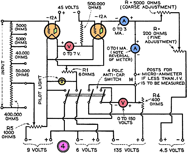
Fig. 4 - The complete circuit diagram of the vacuum tube voltmeter, an instrument which is fast gaining favor with the more serious-minded servicemen and experimenters because of the high degree of accuracy in measurement work which can be attained by its use. We might call attention at this point to the change in polarity of meter A in Figs. 2 and 3. When connected as in Fig. 2 an impressed voltage will cause an increase in the reading; but when the amplifier tube is coupled to the voltmeter tube, the rise in plate current through the latter will decrease the plate current through the ammeter. Now we will discuss the problem involved in the design and construction of the apparatus for laboratory work. One of the first prerequisites for such an instrument is the necessity of constancy of result. If a reading is taken at one time, we shall want a reading repeated at some later date to agree with the first. Also, since no one can say for what purpose the apparatus will be used eventually, we shall want a range from the lowest to the highest voltage that is likely to be measured. A further desirability is the inclusion of some method whereby the apparatus can be made ready for use without the necessity of laboratory standards of any sort. In order to make sure of the first condition it is necessary only to make certain that all part are the finest obtainable, and that the batteries and meters used are in good condition. To make our instrument meet any reasonable demand for range, we might make use of the input arrangement shown in Fig 4. This is essentially a non-inductive potentiometer, and is so arranged that the load upon the circuit to be measured is constant at 500,000 ohms. The values of separate resistances we used are indicated in Fig. 4. We can satisfy the last requisite by a novel arrangement for setting the meters. If the reader will refer to Fig. 4, as he proceeds, he should have no difficulty in following the discussion. Its Use The first adjustment is that of filament voltage, accomplished through the rotation of R1. With the filaments set at five volts the plate voltmeter "V" is adjusted to read 130 volts by means of rheostat R4. R5 is now turned until the plate current through the amplifier tube is 2.5 milliamperes. This adjustment is the key to the whole affair; it will be noticed that by adjusting the grid bias of one tube, we automatically adjust the plate current through both tubes to their correct value. The concluding adjustment is carried out by adjusting "R" until the milliammeter "A" reads zero. A study of the photographs will give a good idea of the method used in constructing the model. A top panel is made of aluminum 1/4" thick, the edges were chamfered, and the top given a silvery satin finish by fine emery and steel wool.
The vacuum tubes are slung beneath the panel, only a portion of their tops protruding above. The shield caps which cover them are in front of the case. In order to make the apparatus as unvarying as possible, it was wired with sturdy No. 12 round bus bar covered with spaghetti. Resistance values as well as meter ranges are indicated in Fig. 4. Binding posts were placed at point "m" These binding posts are short circuited during normal use. If, however, we wish to cover a range such as 0-.1 volt with a full-scale deflection, the jumper is removed and a zero to two hundred micro-ammeter substituted. Since this meter can be used on either a.c. or d.c., we may calibrate on d.c. and use it on a.c. A distinct advantage of the method used to multiply the range is that it can be calibrated at anyone range and will then be accurate for all ranges. It is of course understood that the input resistances should be exact in values. A good d.c. voltmeter of convenient range may be used in calibrating. The finished instrument will come in handy in any experimental laboratory where an exact knowledge of circuit behavior is desired. It can be used to measure the gain of audio amplifiers, radio amplifiers, total gain of sets, loud speaker performance, microphone characteristics, and for a great many other measurements. Through its use we can find out how an amplifier behaves at different frequencies and with different circuit characteristics. A future article will explain how some of these measurements can be made.
Posted December 18, 2023 |
|

 100 kΩ
(see diagram to left). If the open circuit "true" voltage level is 11 V, then
voltage division effected by the 100 kΩ meter in series with the DUT's 10 kΩ
internal resistance would produce a VOM reading of 10 V (ten elevenths of 11
volts) - clearly incorrect. In the days before FET (field effect transistor) input
multimeters, when most volt-ohm-milliammeters (VOMs) consisted of a series of selectable
voltage division circuits and a current-driven
100 kΩ
(see diagram to left). If the open circuit "true" voltage level is 11 V, then
voltage division effected by the 100 kΩ meter in series with the DUT's 10 kΩ
internal resistance would produce a VOM reading of 10 V (ten elevenths of 11
volts) - clearly incorrect. In the days before FET (field effect transistor) input
multimeters, when most volt-ohm-milliammeters (VOMs) consisted of a series of selectable
voltage division circuits and a current-driven