|
Jun/Jul 1958 National Radio News
 Table
of Contents Table
of ContentsThese articles are scanned and OCRed from old editions of the
National Radio News magazine. Here is a list of the
National Radio News articles I have already posted. All copyrights are hereby acknowledged. |
Here is my certificate for completing a National Radio Institute
(NRI) electronics technician course in 1987, just before beginning my BSEE junior
semester at University of Vermot.
Many people find their way to RF Cafe as a result of a Google (or other) search
about electronics, so even though regular visitors might find this primer on Ohm's
law to be a redundant review (is that phrase redundant?), it will be valuable to
the aforementioned people. Electronics technology has moved forward at lightning
speed in the last century, but the fundamentals of Ohm's law remain unchanged -
at least in the Newtonian physics realm. Indeed, we would be in trouble if voltage
no longer equaled the product of current and voltage (E = I x R).
National Radio-TV News magazine was published monthly (1928 - 1980) by
National
Radio Institute, a correspondence school that did business from 1914 through
2002. A bonus electronics-themed comic is included.
How Ohms Law is Used in Service Work
 By Dale Stafford, By Dale Stafford,
NRI Consultant
Ohm's Law defines the relationship between voltage, current, and resistance (in
a dc circuit) or impedance (in an ac circuit). Since resistance and impedance both
refer to the opposition offered to the flow of current, no effort will be made to
differentiate between them in this article. The term resistance will be used to
refer to any opposition to current flow.
The current flowing in a circuit or through any part in a circuit depends on
two things: (1) the voltage applied across the circuit or part and (2) the resistance
of the circuit or part.
The current is directly proportional to the applied voltage. It will vary in
direct proportion to any changes in the voltage. If the voltage is increased without
changing the resistance, the current will increase. If the voltage is reduced without
changing the resistance, the current will decrease. If the voltage is doubled, the
current will double. If the voltage is cut in half, the current will be cut in half,
also.
The current is inversely proportional to the resistance and will vary inversely
with any change in the resistance. If the resistance is increased without changing
the applied voltage, the current will decrease. If the resistance is reduced without
changing the applied voltage, the current will increase. If the resistance is doubled,
the current will be cut in half. If the resistance is cut in half, the current will
be doubled.
These relationships make it easy for us to find one of these values if the other
two are known. Three formulas are used for these computations. They are:
I = E ÷ R
R = E ÷ I
E = I x R
In these formulas E stands for the applied voltage, R stands for resistance,
and I stands for current. In calculations involving ac circuits, Z, which stands
for impedance, is substituted for R in the formulas. Otherwise the formulas are
the same.
Just why is Ohm's Law so important to the serviceman? Only on rare occasions
is it necessary for him to use it in finding the value of a part needed as a replacement.
Ordinarily, diagrams are available giving the value of the parts used in a radio
or TV receiver. He needs only to glance at the diagram to obtain the information
he needs.
The answer is that he uses Ohm's Law (perhaps unconsciously) every time he attempts
to locate a defect in a receiver by measuring the operating voltages or taking resistance
measurements. For example, suppose he finds that the voltage across a cathode bias
resistor is too high. Because E equals I x R, he immediately knows that
the resistor has increased in value or that the tube is drawing too much current.
Or suppose he finds the voltage too high on a screen grid that has a dropping
resistor between the grid and B plus. At once, he suspects that the resistor has
decreased in value or that, for some reason, the tube is not drawing normal screen
current.

"You don't have to fix it young man - just find it!"
The complaint may be a severe case of distortion. When our technician connects
his VTVM across the grid resistor in the output stage, he finds a positive dc voltage
on the grid. Normally, the grid does not draw current, and with no current through
the grid resistor, there should be no voltage drop across it. Pulling the output
tube (if it is an ac set) or disconnecting the coupling capacitor (if it is an ac-dc
set) will enable the serviceman to determine if a gassy output tube or a leaky coupling
capacitor is responsible for the trouble.
Another condition often encountered is that of an excessive voltage drop across
a decoupling resistor in the plate circuit of a tube. This might be caused by a
change in the value of the resistor. It could also be caused by some defect that
caused the current through the resistor to increase, such as a leaky bypass capacitor
on the plate side of the resistor, a shorted cathode bias resistor or bypass capacitor,
or a defective tube.
It does not take a very large change in resistance or current to cause a considerable
increase in the voltage drop across the resistor with a corresponding decrease in
the voltage available at the plate of the tube.
Even if the serviceman does not know what the plate voltage or the voltage drop
across the decoupling resistor should be, a tube manual will usually give him this
information. These manuals list operating voltages and currents for typical operating
conditions and a comparison of these voltages with those available in the receiver
will usually make it possible to determine the approximate correct value.
These and many, many others are all practical applications of Ohm's Law. Automatically,
almost unconsciously, the serviceman uses Ohm's Law to analyze circuit conditions
even though he doesn't sit down with paper and pencil to calculate exact values.
However, there are certain occasions when he may find it necessary to make such
computations. One such occasion might be in computing the value of a series voltage-dropping
resistor in the filament circuit of a radio receiver. In ac-dc receivers, the tube
filaments are connected in series and connected across the power line. If the voltage
required for the tubes is less than the line voltage, it is necessary to insert
a voltage-dropping resistor in the filament circuit to use up the excess voltage.
This resistor may burn out, leaving no clue to the proper value.
To find the value of this resistor, it is first necessary to find out how much
voltage must be dropped across it. Adding the voltage drops across all the tubes,
and subtracting this figure from the line voltage gives us this value. Of course,
tubes in these sets are designed to operate with the same value of filament current,
and this current must also flow through the resistor. Dividing the voltage drop
across the resistor by the filament current gives us the value of the resistor.
If the resistor is a chassis-mounted resistor, it is necessary to compute the
required wattage rating of the replacement to be sure that the necessary amount
of heat can be safely dissipated. This can be found by multiplying the voltage drop
across the resistor by the resistor current. To allow a margin of safety, a higher
value should be used (at least 1-½ times the computed value).
If a line-cord resistor is used, there is no need to figure the wattage as these
resistors can dissipate more heat than they will ever be required to.
A serviceman may find it necessary to figure the value of a cathode bias resistor
to be used in a circuit he is wiring or to replace a burned-out resistor whose value
is unknown. A cathode bias resistor carries the plate and screen-grid currents of
the tube. The current through the resistor can be found by adding the plate and
screen-grid currents which will flow at the value of plate voltage used. Again a
tube manual can be used to determine the approximate value.
The bias voltage developed across the resistor will be equal to the current through
the resistor multiplied by the value of the resistor (E equals I x R). The proper
resistor value can be found by dividing the bias voltage needed by the current through
the resistor (sum of plate and screen grid currents).
Pilot lamps in many receivers are connected in series with the tube filaments.
When this is done, it is necessary to protect the lamp against excessive current
flow. This can be done either by shunting the lamp across a portion of the rectifier
tube filament or by connecting a small resistor in series with the filament circuit
and connecting the lamp across the resistor.
The resistor is chosen so that the voltage drop across the resistor and lamp
will be 4.25 volts when the normal filament current is flowing. The resistor must
carry a current equal to the difference between the current rating of the lamp and
the current rating of the tubes.
The proper resistance value can be found by subtracting the current rating of
the lamp from the current rating of the tubes and then dividing 4.25 by this figure.
Many other applications of Ohm's Law will be encountered in practical servicing
work. The busy technician uses his knowledge of this subject every hour of every
day. Whether he uses it to figure the exact value of a new or replacement part or
merely to interpret the meaning of measurements he has taken, he finds it one of
the most valuable "tools of the trade."
There are other reasons why the student of electronics should know the subject
thoroughly. Not every student starts his own shop when he completes his training.
Many go to work for others. Before a company hires a technician, he will be required
to take a written or oral examination to prove that his training is adequate. Quite
likely several of the questions will be on practical applications of Ohm's Law.
Those who go to work for someone else may find themselves helping to design and
construct circuits of many kinds. Perhaps one may be helping an engineer with design
work while another is doing maintenance work on old circuits that must be modified
or rewired.
If one of these men is asked by his superior to compile certain information,
he must know how to obtain that information as quickly and accurately as possible.
For example, if he is asked for the current flow through a resistor, he should know
that measuring the voltage drop across it and dividing this figure by the value
of the resister is a quicker and easier method of finding the current than actually
measuring the current with a meter. To measure the current, the circuit must be
broken so the meter can be inserted in series with the current, the measurement
must be taken, the meter removed, and the circuit reconnected. Unless the meter
is connected as a permanent part of the circuit, the first method is, naturally,
preferable.

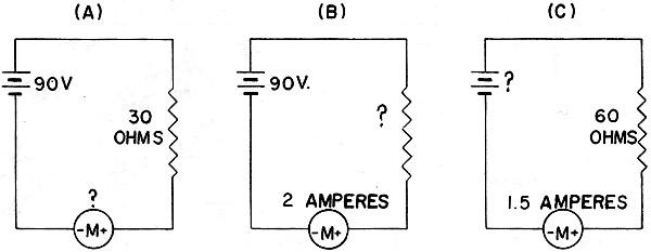
Fig. 1 - Ohm's Law in use.
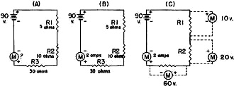
Fig. 2 - Ohm's Law in dc series circuits.
The following are some examples of Ohm's Law in use:
In Fig. 1(A), we have a simple dc circuit consisting of a resistor in series
with a battery.
If we know the battery voltage and the resistance, we can find the current. Suppose
the battery voltage is 90 volts and the resistance is 30 ohms. Since I = E ÷ R,
the current through the resistor is 90 divided by 30, which equals 3 amperes.
If the battery voltage and the current are known, as shown in Fig. 1(B),
the resistance can be found. Here the battery voltage is 90 volts and the current
is 2 amperes. R = E ÷ I, so the resistance equals 90
divided by 2, or 45 ohms.
If both the resistance and current are known, the battery voltage can be found.
(Fig. 1(C). Here the resistance is 60 ohms and the current is 1.5 amperes.
E = R x I, so the battery voltage equals 60 x 1.5, or 90 volts.
The same procedure can be used in simple dc series circuits containing several
resistance values in series, as shown in Fig. 2.
In Fig. 2(A), we have three resistors of known value in series with a 90-volt
battery. The first step in finding the current is to add the value of all the resistors
to find the total circuit resistance. (Rt = R1 + R2 + R3,
5 + 10 + 30). We find the total resistance to be 45 ohms. Then,
using the formula E+R=I; we have 90 divided by 45, which equals 2 amperes, the circuit
current.
In Fig. 2(B), we have three resistors of known value in series with a battery.
If the circuit current is known, we can use the formula E = I x R
to find the voltage across each resistor, since in a series de circuit the same
current flows through each part in the circuit. In this case, 5 x 2 equals
10 volts (the voltage across R1), 10 x 2 equals 20 volts (across R2),
and 30 x 2 equals 60 volts (across R3).
In Fig. 2(C), we have the same circuit except that we do not know the value
of the resistors. Since R = E ÷ I, it is easy to find the total resistance
of the circuit by dividing the battery voltage by the circuit current. However,
we need to know the voltage drop across each resistor to find the value of each.
Measuring these voltages, suppose we find 10 volts across R1, 20 volts across R2,
and 60 volts across R3 as shown by the dotted lines in the figure. Then 10 divided
by 2 equals 5 ohms (value of R2, 20 divided by 2 equals 10 ohms (value of R2), and
60 divided by 2 equals 30 ohms (value of R3).
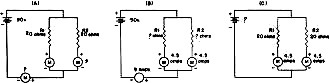
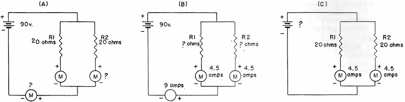
Fig. 3 - Ohm's Law in dc parallel circuits.

Fig. 4 - Circuit problems (answers at bottom of page).
We can find unknown values In parallel dc circuits in the same manner. In Fig. 3(A),
a 90-volt battery is connected in series with two parallel-connected 20-ohm resistors.
Since I = E ÷ R, the circuit current will be equal to 90 volts
divided by the equivalent resistance of the parallel-connected resistors. Let's
see how to find the equivalent resistance.
If resistors of equal value are connected in parallel, the equivalent resistance
of the combination is equal to the value of one of the resistors divided by the
number of resistors used. In this case, 20 divided by 2 equals 10 ohms. Had the
resistors been of unequal value, the formula
 could have been used
to find the equivalent resistance. could have been used
to find the equivalent resistance.
The circuit current will be 90 divided by 10, or 9 amperes. In a parallel circuit,
the total current divides among the various branches in proportion to the resistance
of each branch. Since the resistors are equal in value, each branch will draw half
the total current, or 4.5 amperes.
In Fig. 3(B), we know the battery voltage and the circuit current, but,
to find the value of each resistor, we need to know the current flowing in each
branch. Suppose we measure these currents and find 4.5 amperes flowing through each
branch.
When a voltage is applied across a parallel circuit, this voltage appears across
each of the branches, so, using the formula R = E ÷ I,
the value of each resistor equals 90 divided by 4.5, which equals 20.
In Fig. 3(C), two 20-ohm resistors are connected in parallel with 4.5 amperes
flowing in each branch. Since E = R x I, we can find the source
voltage by multiplying 20 by 4.5. This gives us 90 volts, the battery voltage.
Ohm's Law could be applied to an ac circuit with equal ease if it were possible
to have such a circuit which was purely resistive in nature. However, when capacity
and inductance are added to a circuit, the procedure becomes somewhat more involved.
Special formulas must be used to figure the reactance of the parts and the impedance
of the circuit. Once this is done, Ohm's Law can be used as easily as in dc circuits.
In Fig. 4 are some problems which can be used for practice. In Figs. 4(A)
and 4(C) you are to find the current. In Fig. 4(B) you are to find the voltage
drop across each resistor. The answers will be found printed upside down below Fig. 4.
Answers: Fig. 4(A), 0.25 amp.; Fig. 4(B), R1 - 3.2
volts, R2 - 4 volts, R3 - 2.4 volts; Fig. 4(C), 0.5 amp.
Posted August 15, 2023
(updated from original
post on May 15/4/2018)
|