|
Being able to quickly interpret
oscilloscope waveforms is essential to efficient circuit design, adjustment, and
troubleshooting. Knowing tell-tale signatures of signal-corrupting influences from
unintended resistance, capacitance, inductance, and nonlinear devices (semiconductors
and vacuum tubes) is a huge advantage when using an o-scope. Equally important is
not introducing waveform- and function-altering effects with probing techniques
and/or incorrect operation of the test equipment. One often seen example of the
latter is using equipment whose input impedance is not proper for the unit under
test (UUT); e.g., wrong impedance coaxial cable in RF situations or too low of an
input impedance for low frequency applications that either loads the circuit to
the point of malfunction or where the voltage division is significant enough to
cause improper readings on the display. Note the interesting comment at the beginning
of this October 1945 Radio News magazine article regarding restoration
of transmitting privileges for amateur radio operators at the end of World War II.
The Oscilloscope Applied to Transmitter Checking
With permission to return to the air, amateurs should recheck their transmitting
equipment. The oscilloscope is an ideal instrument for this purpose. Follow the
procedure outlined herein.
By Morris Eddy and Arthur Howard
|

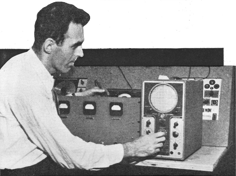
Radio technician applying the oscilloscope in checking transmitter.
|
In a previous article, appearing in the September, 1944 issue of Radio News,
we discussed the application of the oscilloscope to radio servicing. In this article,
we will endeavor to demonstrate how the oscilloscope is used to check the operation
of the transmitter.
The cathode-ray oscilloscope is the most valuable of all instruments in determining
transmitter performance. It provides an instantaneous picture of what is actually
happening inside the transmitter - thus, enabling the operator to determine the
source of any possible defect in the apparatus. This versatile instrument is particularly
suitable for r.f. or a.f. measurements, because it draws little or no power from
the source. Where high speed analysis of performance is required, such as on the
assembly line, the merits of the oscilloscope are once again realized.
The following are some of the uses to which the oscilloscope can be put for determining
the operation and securing maximum results from your transmitter.
Since it is possible for one to observe r.f. with an oscilloscope, it can thus
be readily used as a resonance indicator. Should plate current meters be included
in the transmitter, the use of the oscilloscope is not necessary. If meters are
not included, the oscilloscope can be used as a temporary expedient.
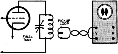
To use it as an indicator for determining resonance, connect a coil of one or
more turns of wire to the vertical axis of the 'scope by means of a twisted pair
line. Any sweep frequency can be utilized. Place the coil near the tank circuit
of the stage being tested and a band should appear on the screen of the 'scope.
The width of this band can be regulated by the number of turns of the coil and its
distance from the tank. The load of the stage, such as the link coupling, grid coil
of the next stage, or the antenna tuner is left on the resonant stage being tested,
so that actual working conditions are observed. Your next step consists of rotating
the tank condenser slowly, until maximum bandwidth is observed on the oscilloscope.
When this condition is reached, the stage is at its desired resonance. Fig. 1
shows the necessary hookup.
In the above manner, all stages of the transmitter can be aligned and faults
existing in a stage of a transmitter can be traced to that particular stage.
Neutralization Indicator
|

Fig. 1. When applying the oscilloscope to determine resonance
of the tube circuit, the 'scope is loosely coupled as shown.

Fig. 2. Any defects in the speech-amplifier equipment can
be easily checked by employing, along with the oscilloscope, an audio frequency
oscillator, connected as shown
|
Because of the property of the oscilloscope of not drawing any appreciable power
from a circuit, it makes a fairly sensitive neutralization indicator. In cases of
emergency, it can be substituted for the regular indicating device.
To determine whether or not a stage is properly neutralized, turn on the filament
of the chosen stage and apply excitation from the previous r.f. amplifier to its
grid circuit. Be certain that the plate voltage is turned off. Use the same coil
and twisted wire line as shown in Fig. 1. Hold this coil near the plate tank
coil of the stage under test. Next, tune the condenser through resonance and, at
resonance, no r.f. waves should appear on the screen, provided the stage is properly
neutralized. If r.f. is present, adjust the neutralizing condenser with an insulated
screwdriver until there is no r.f. remaining on the screen of the scope.
In push-pull circuits, both neutralizing condensers are adjusted simultaneously,
i.e., step by step, until there is no r.f. present.
Checking Modulation Equipment
Any defects in the speech amplifier equipment can be determined with the use
of the oscilloscope. Faults indiscernible to the human ear are made apparent with
this instrument.
First, connect an audio oscillator to the input of the speech amplifier equipment
in place of the microphone. Take the output off the final stage of the modulator.
Next, synchronize the sweep oscillator of the 'scope with the audio frequency. Refer
to Fig. 2 for the diagram.
By comparing the original waveform of the a.f. oscillator with that of the output
of the final stage, you can determine the quality of your modulating equipment.
If distortion is present, it can be traced down to the individual stage causing
this condition.
To localize the distortion to the stage causing it, proceed as follows:
Connect an a.f. oscillator to the input terminals of the speech amplifier. Then,
connect the oscilloscope successively to the output stage of each of the tubes in
the amplifier, starting with the preamplifier stage, and working toward the output
stage.
As we proceed in this manner, the gain of the amplifier will increase. To compensate
for this, decrease the amplifier gain control of the oscilloscope. This is necessary
in order to prevent overloading the oscilloscope. Once the faulty stage is located,
it should be serviced accordingly.
Another trouble frequently encountered by the operator is phase distortion. This
condition occurs when the phase relationship of two or more factors in the amplifier
circuit is altered. This condition can be usually rectified by changing the circuit
constant (RC values).
Typical Trapezoidal Patterns Showing Transmitter Operation
|
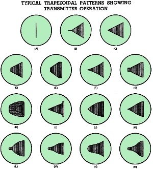
Typical trapezoidal patterns showing transmitter operation.
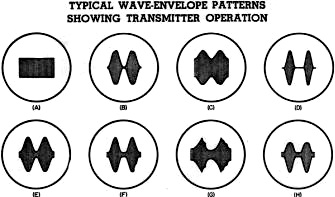
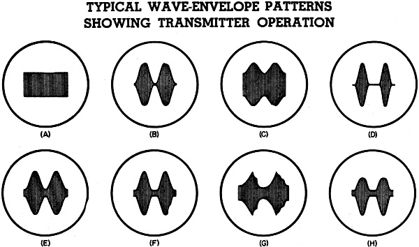
Typical wave-envelope patterns showing transmitter operation.
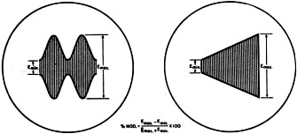
Method of determining modulation percentage of trapezoidal or
wave-envelope patterns.
|
(A) Unmodulated carrier. (B) Over 100% modulation - distortionless wave. (C)
Illustrating distortionless 100% modulated wave-ideal pattern. (D) Less than 100%
modulation-wave contains no distortion. (E) Pattern illustrates two possible troubles.
Insufficient r.f. grid excitation to modulated amplifier or lack of sufficient filament
emission. (F) Pattern illustrates regeneration in class "C" stage. which is due
to too much bias or improper neutralization. Note curved sides of pattern. (G) This
trace is due to mismatched class "B" modulator to the class "C" load. (H) In this
pattern we have a condition of phase shift. This is due to the fact that the audio
voltages were not taken directly from the output of the modulator. (I) This pattern
shows that parasitics are present on the positive modulation peaks in the modulated
amplifier. (J) Insufficient excitation or bias applied to a triode (plate modulated
zero bias) will cause this trace. (K) Approximately 100% modulated (grid or cathode)
wave. (L) Approximately 100% suppressor modulated wave. It uses separate r.f. driver.
(M) This trace shows a poorly regulated r.f. driver or it can also be the result
of excessive excitation. (N) Diagram of a grid modulated phone wave. It is not properly
neutralized and also lacks proper reactive load. (O) A suppressor modulated wave.
Circuit uses an 802 or 804 and has a crystal in the grid circuit.
By using the above procedure, audio distortion, improper operation due to incorrect
bias, phase distortion, etc., are readily detected. If desired, the overall frequency
response of the amplifier can be approximated by varying the audio oscillator frequency
and noting the changes, if any, in the amplitude of the trace. It is essential that
the output of the a.f. oscillator used be kept constant. For those wishing more
accurate knowledge of the frequency response of the audio apparatus, a graph thereof
should be made.
Modulation in Radiotelephone Transmitter
Perhaps the most frequent use of the oscilloscope is for observing modulation
characteristics in radiotelephone transmitters. The oscilloscope can be utilized
to disclose the modulation percentage, linearity, and power output available from
the audio-modulator - without distortion.
Two types of patterns are regularly employed for checking the performance of
radiotelephone transmitters. These are the wave-envelope and trapezoidal patterns.
Each pattern tells much about the operation of the transmitter. For ordinary purposes,
either one may be used. However, for a more exacting determination of performance,
both types of patterns should be employed, thus getting a better delineation of
the transmitter capabilities.
The wave-envelope pattern is the easiest to hook up and gives an overall picture
of the audio amplifier, modulator, and modulated amplifier. Any change in the waveform
of the speech amplifier will produce a corresponding change in the wave pattern.
(A) Unmodulated carrier wave. (B) 100% modulation - ideal pattern to get. (C)
Less than 100% wave. (D) Greater than 100% modulation (overmodulation). (E) This
type of pattern is due to insufficient grid excitation to the final modulation stage.
(F) This is a condition of overmodulation (greater than 100%) with the addition
of audio distortion. (G) When the plate circuit of the modulated amplifier is not
at the proper resonance, the trace, as shown, will be the result. (H) This type
of pattern is due to overloading or rectification in the oscilloscope's amplifier.
Values for voltage divider should be determined by trial, as they depend on the
oscilloscope used.
Usual values are:
R 1- 0.5 megohm, 1 w. res.
R2 - 50,000 ohm, 1 w. res. (low power)
R2 - 10,OOO ohm, 1 w. res. (high power)
For direct connection, R2 is a potentiometer with C1 attached
to moving arm.
R2 - 0.2 megohm pot. (high power).
R2 - 0.5 megohm pot. (medium power)
R2 - 0.5 megohm pot. (low power)
(R1 should be shorted when used on low power)
|

Fig. 3. - Diagram showing oscilloscope connections for obtaining
trapezoidal patterns when checking grid, suppressor, or screen modulated type transmitters.
|
The waveform should be sinusoidal if the modulator is functioning correctly. A change
in the audio frequency of the oscillator will necessitate a corresponding change
in the sweep circuit.
In contrast, when observing a trapezoidal pattern, changes in audio frequency
or waveform of the audio oscillator will not produce a change in the general shape
of the pattern, provided the modulation percentage is constant. Thus, the trapezoidal
pattern indicates only modulation percentage and linearity of the modulated r.f.
amplifier.
Typical waveform and trapezoidal patterns illustrating different modulating conditions,
etc., are included. These should be referred to and studied. For critical examination,
the proportions as shown on the typical characteristic sheets should correspond
closely with the waveforms and trapezoidal patterns appearing on the screen.
The great advantage of the trapezoidal pattern over the wave-envelope pattern
is that a microphone can be substituted for the audio oscillator and the effect
of the operator's voice will be noted. The figure expands and contracts horizontally
as the operator talks, completing the triangle as one hundred percent modulation
is approached. Overmodulation is indicated by a dashed horizontal line extending
from the vertex of the triangle.
If the same process as outlined above is carried out with the wave-envelope pattern,
a meaningless jumble appears across the screen, because the sweep circuit is not
synchronized with the speech. This effect can be counteracted to some extent by
the following method. Apply a strong synchronizing voltage, taken from the pre-amplifier
stage, to the synchronizing jacks of the sweep oscillator. This measure should make
the trace more constant. Individual waveforms separated by short, bright dashes
indicate overmodulation.
To determine the 60 or 120 cycle hum level of the transmitter in question, using
the wave-envelope pattern, proceed as follows:
No a.f. signal is fed to the speech amplifier so that the figure appearing across
the screen is a band (like an un-modulated carrier). Then, adjust the sweep circuit
to a submultiple of the power line frequency, such as 20 or 30 c.p.s. If ripples
or humps appear across the screen, extraneous modulation due to the power line is
occurring. On the other hand, the trapezoidal pattern indicates immediately whether
there is appreciable hum or noise modulation of the carrier.
Methods of Connection
The connections for the wave-envelope pattern, as stated above, are much simpler
than those of the trapezoidal pattern. The method consists of feeding some of the
output of the modulated amplifier to the vertical axis. This is done with a coil
of one or more turns of wire fed to the input terminals by means of a twisted pair.
On high frequencies (100 kc. and above) direct connection should be made to the
vertical deflector plates of the scope. This measure is necessary because the amplifier
contained in the instrument is not capable of handling high frequencies.
The sweep circuit is synchronized with the audio oscillator that is fed to the
input of the speech amplifier equipment. To do this, feed the audio output from
the oscillator to the synchronization terminals through a 0.01 μfd. condenser.
The height of the pattern is varied by changing the number of turns of the coil
or its distance from the output tank. The load, antenna, or antenna tuner is left
connected to observe performance under actual working conditions. With the sweep
circuit properly synchronized and at a multiple of the audio oscillator frequency,
an image appears with several sine waves. By increasing the audio oscillator output,
the percentage of modulation is correspondingly increased. By this method, all types
of modulation may be observed including plate, grid, screen, and suppressor modulation.
Fig. 1 shows the necessary hookup.
Posted May 2, 2022
(updated from original post on 4/29/2015)
|