|
November 1946 Radio News
 [Table
of Contents] [Table
of Contents]
Wax nostalgic about and learn from the history of early
electronics. See articles from
Radio & Television News, published 1919-1959. All copyrights hereby
acknowledged.
|
Imagine if you wanted to
transmit from your car with a 400 kHz radio and had to trail a 600-foot-long
¼-wave wire antenna behind to do it. Of course nobody ever did that, but it was
common practice with airplanes in the days before VHF and UHF communications
became the norm. It wasn't because nobody knew that it would be more
advantageous to operate at higher frequencies in order to reduce antenna size
requirements, it was that electronic equipment capable of withstanding the
rigorous environment of airborne conditions was not ready for prime time, as the
saying goes. Come to think of it, the term "prime time" had probably not even been coined yet when this article
was written in 1946 because it derives from the evening television viewing hours
(~8:00 to 11:00 pm) when the most viewers were tuned in. Electric and/or manual
winches were used to deploy the antenna after getting airborne and to reel it in
prior to landing. Weights were hung on the end in order to prevent oscillations,
but that was dangerous both to the aircraft and people and objects on the ground
when a length of wire and the weight would beat on the airframe during winching
or would break off and fall to Earth.
Planning an Aircraft Radio Installation
By J. D. Scalbom
Sales Engineer, Bendix
Radio Division of Bendix Aviation Corporation
The owner's desires, facilities available, and the type of plane are factors
which must be carefully considered.

Fig. 1 - Beechcraft model D185 all-metal, twin-engine 6
to 10 place monoplane.
This discussion is planned to bring to the reader's attention the practical points
to be considered in the planning of an aircraft radio installation. With large fleets
of identical aircraft, such as in airline operations, it is possible to arrive at
a set of highly useful and accurate data. When the variety of aircraft types encountered
increases, the most practical results are obtained through the application of good
sense and ingenuity, coupled with past experience and acquaintanceship with the
equipment being considered for the installation. This is particularly true of the
antenna types and placement.
The problems involved in planning an installation of radio gear in the small,
two or three place "family" type aircraft requires considerable care and thought.
The entire problem is not nearly so complex as with the larger aircraft that are
being put into use for private transportation by many large organizations. This
latter group will be dealt with because the former class will then be covered automatically.
The first phase of the planning resolves into what choice of facilities is required
or desired by the owner; and these specifications must then be met as completely
as is practical, considering the aircraft in question, etc.
The aircraft used as "executive" transports are comparable to the commercial
airline craft in speed and their ability to fly under very adverse weather conditions.
Due to the nature of the flight operations these aircraft must be equipped with
a radio "system" which will allow full use to be made of the government and private
navigational and safety facilities. The high degree of reliability achieved in commercial
airlines operations is very dependent upon these same aids. Without a complete coverage
of the available aids much of the usefulness of the aircraft is sacrificed. The
"executive" transport must be capable of going anywhere, and at any time that commercial
airlines are operating.
Radio Facilities Available
Navigational and safety aids operating within the frequency range of 200 to 400
kilocycles include several types. Airways range stations are the best known of these.
Each range station consists of an antenna system keyed by "A" (dit-dah) and "N"
(dah-dit). In the "quadrants" either an "A" or "N" is received while along a range
leg or "beam" the field strengths of the antenna towers approach equality. With
equal signals the "A" and "N" keying blends into a steady audio signal. At regular,
short intervals an identification code is transmitted. Airways charts show the placement
of each range station and the direction of the range legs from that station.
At designated times during each hour weather broadcasts are made from these stations.
They may also be contacted for weather and traffic information. Emergency services
are handled, too, but not messages of a personal nature. Much has been written covering
this highly important network so that no more need be said here concerning it. In
addition to the range stations non-directional homing stations are located at strategic
points to provide aural-null direction finding (DF), or automatic direction finder
(ADF) fixes. These are of particular use for traffic "holding" points adjacent to
large airports. Airways and airport control towers also operate in this frequency
range, 200 to 400 kilo-cycles.
Very-high frequency (v.h.f.) facilities are being installed to serve the same
purposes as just mentioned. To date only a small portion of the airways have been
converted for v.h.f. navigational usage. However, the CAA (Civil Aeronautics Authority)
towers are equipped and are standing by for communications on v.h.f. By July, 1946
all CAA towers and at least 100 range stations were ready with v.h.f. for communications.
Navigational facilities will require some time for completion, however. The low
frequency radio ranges are still entirely intact, and will remain in service for
an indeterminate period. Of course new radio gear must also be developed to make
full use of the potentialities which v.h.f. offers. The frequency range of 108 to
132 megacycles has been assigned for this service. Immediately available for use
by the itinerant or private pilot are 131.9 megacycles for air-to-ground airport
control tower contacts and 131.7 megacycles for air-to-ground airways communications
station contacts. For the time being ground-to-air transmissions remain in the 200
to 400 kilocycle band.
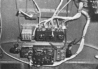
Fig. 2 - Beechcraft C-45 cockpit with military type radio controls installed.
These v.h.f. itinerant flyer's frequencies were assigned on a temporary basis,
but final permanent allocations have been recently announced by the FCC. The permanent
assignment for airport control towers is 122.5 mc. and for airways communications
stations, 122.1 mc. The CAA has announced that as of January 1, 1947 its facilities
will be guarding these new frequencies, but until that date guard will be maintained
on 131.9 and 131.7 mc. Aircraft radio station licenses in force on v.h.f. at the
time of changeover will be automatically carried over to the permanent frequencies
without reapplication by the license holder.
Of great importance to navigation and safety is the system of "marker beacons"
operating on 75 megacycles. Several functions are served by these marker beacons.
The "Z" marker located at the range station site has a field strength pattern vertical
and conical so as to give a positive indication of range station location. (This
is opposite to the "cone of silence" which is a negative indication in that the
range receiver signal momentarily reduces over the range station. This phenomenon
is due to signal cancellation between the radio range station antenna field patterns.)
"Fan" markers located at distances varying between approximately 10 and 30 miles
from range stations adjacent to major airports and along the range legs provide
the pilot with absolute "fixes" especially useful in instrument approach problems.
The "Airways" or "Fan" and the "Z" markers are modulated by 3000 cycle audio and
by means of audio filters, etc., employed in the marker receiver a white "Airways"
indicator light is made to light up giving a visual indication in addition to the
audio signal. A marker receiver is indispensable to instrument flight operations.
In like manner "Outer" and "Inner" markers are located on the instrument approach
path to an airport. The "Outer" marker is distinguished by a 400 cycle audio note
and a blue indicator light; the "Inner" marker by a 1300 cycle audio tone and an
amber light.
3105 kilocycles and 6210 kilocycles are the itinerant flyer frequencies in addition
to the recently allocated v.h.f. channels. The commercial airlines operate on frequencies
between 2.8 and 12.5 megacycles.
Little use has been made of the "ship-to-shore" radio network linking shipboard
telephones with landlines, but it is expected that advantage will be taken of the
personal type of service offered since no personal messages can be handled by the
facilities so far mentioned. Most of these stations operate in the 2.0 to 2.5 megacycle
range.
Proposed Minimum Radio System
The preceding outline of services has been made to show the need for each of
the pieces of gear recommended as a complete, minimum radio "system" to be carried
aboard the "executive" class of aircraft. Additional v.h.f. instrument approach
gear might be considered in the large aircraft in the DC-3 class; however, such
equipment is far beyond practical consideration for the medium sized 6 to 8 place
aircraft. The following units comprise a minimum for "night instrument" operations:
1. An ADF (automatic direction finder) covering a frequency range of at least
200 to 400 kilocycles. (550 to 1200 kilocycles in addition is desirable). ADF bearings
on frequencies higher than approximately 1200 kilocycles are questionable although
"homing" is usually satisfactory.
2. A second receiver having a frequency range of at least 200 to 400 kilocycles
for tower and airways contacts while the ADF is used for navigation, and for range
flying. The use of a fixed or rotatable antistatic loop antenna, too, is highly
recommended for use with this receiver. Aural-null bearings may be taken with such
a loop antenna.
3. A 75 megacycle marker receiver having audio as well as visual indication.
At least a single indicator light which responds to all of the marker beacons ("Airways,"
"Inner" and "Outer" markers) without giving spurious indications (as when passing
over power lines, or showing a light when the transmitter aboard the aircraft is
operated), must be part of this piece of gear.
4. A transmitter operating on 3105 and 6210 kilocycles having a reliable range
equal to 20 minutes flight at cruising speed of the aircraft. Antenna efficiency
rather than transmitter power is a limiting factor in fulfilling this requirement.
5. A control, or set of controls and associated parts which tie the above four
equipments together in such a way as to allow complete selection of the desired
functions from at least the pilot and co-pilot positions. Selection without interference
between either station must be attained. These controls must be easily accessible
and easily seen from either position.

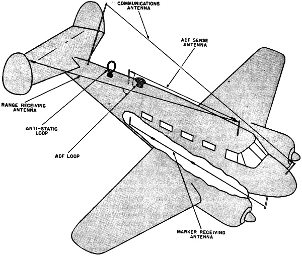
Fig. 3 - Antenna arrangement on typical executive and light
transport type aircraft.
Depending upon the past experiences of the pilots who are in charge of the aircraft,
the radio system may be either increased or decreased and otherwise modified according
to the type of operations these men expect to carry on. Obviously it would be foolish
not to equip an aircraft of unlimited operating ability with a complete set of radio
gear - and the opposite also holds true.
Very-high frequency is rapidly being put into use and a complete system will
require the addition of a low power v.h.f. transmitter having five channels. Two
of these can be used immediately, 131.9 megacycles for air-to-ground control tower
contacts, and 131.7 megacycles for air-to-ground airways communications station
contacts. The three additional channels will be designated for congested areas as
soon as traffic warrants it. An output power of less than one watt will give complete
reliability at 40 to 50 miles at altitudes of 1500 to 2000 feet. Range naturally
increases with increase in altitude over the terrain. Ground-to-air contacts will
remain in the 200 to 400 kilocycle band and present equipment is far from being
obsoleted since a gradual transition period of at least five to eight years is contemplated.
Modification of Military Equipment
Most of the aircraft purchased from the military have a radio system installed
in them which is unsatisfactory from several standpoints. The failings can be overcome
in some degree by modification and rework, however it is almost impossible to obtain
a completely satisfactory radio setup. Compromises of more or less consequences
must be made in every case. The transmitters require modification to provide crystal
control. But then the power is often low and modulation is seldom a full 100%. Coverage
is usually far below that required by high speed aircraft. The receivers themselves
are very good and have adequate frequency coverage. The ADF's are fully satisfactory.
Perhaps one of the greatest difficulties of the military radio system aside from
the transmitter is the inflexibility of the switching of the audio circuits and
the range-voice filters. Paralleling of the pilot and co-pilot audio outputs cannot
be prevented when each receiver has only a single audio output channel. This is
the case with each of the military radio receivers, and transmitter side tone and
interphone. In addition, the control boxes and switches are in several separate
units that are placed throughout the cockpit. A clean appearance and fully satisfactory
cockpit arrangement is practically out of the question. This is not disparaging
to the modifications that have been made since it is simply a fact that the "tools"
available do not lend themselves to the job as well when they have been designed
to do many things, as when they are designed to do a particular job.
Illustrated in Fig. 5 is a C-45 Beechcraft which was modified to overcome
as far as possible the failings just pointed out. The new rectangular control box
takes the place of the triple control formerly used for three military type receivers.
Within this new control box are the following controls:
1. Individual range - voice filter switches, located at each end of the box.
2. "On-Off," channel selector and "Transmit-Interphone" switches, and indicator
lights for a ten channel, crystal controlled, communications unit, which replaces
the military transmitter. (This is a fifty watt transmitter and receiver unit).
This group can be seen to the left of the center of the control panel. See illustration
Fig. 5, shown on page 27.
3. Tuning and audio controls for a single military range receiver having a frequency
range of 195 to 550 kilocycles. These controls were removed from the military control
box, and can be seen to the right of the center (Fig. 5).
4. "Audio On-Off" switches (one for each of the receivers, ADF, range receiver
and communications receiver) are provided for each of the pilots. These are located
along the lower edge of the control panel at each end of the panel.
5. Two hybrid transformers which provide dual audio outputs from the ADF and
range receiver. (The communications receiver unit already has dual audio channels).
6. Two auto-transformers to 'provide impedance matching from high to low impedance
as required with some models of military receivers.
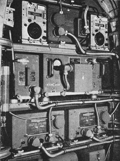
Fig. 4 - Radio gear mounted in the nose of a Lockheed Lodestar.
It can be seen that all controls are ahead of the pilots' line of vision and
complete separation of the audio facilities have been provided. Reasonable cleanness
has been gained, too. The remote crank for a trailing wire antenna reel is within
easy reach of both pilots. Space for this control was made by relocating the ADF
control box to the left of its original position. The military transmitter control
was also removed. A comparison with the original cockpit layout can be made by referring
to Fig. 2.
An "Unmodified" Cockpit Layout
In contrast to the modified installation as just illustrated compare the foregoing
with the new control panel shown in Fig. 7. This is an engineered unit starting
with a completely new set of radio gear. Nothing makeshift has been required. A
single unit takes the place of the several controls required in the modification.
The entire radio system was treated as a unit and engineered from that standpoint.
The advantages gained are obvious, but a few should be pointed out such as; a very
clean cockpit with all radio controls ahead of the pilots' line of vision; ease
of installation; complete use of all facilities offered by the particular units
involved; saving in weight and over-all cost. The control panel illustrated provides
the following:
1. Complete selection of audio outputs by either pilot with no mutual interference.
2. Audio level controls and marker receiver sensitivity control within easy reach
of either pilot.
3. Individual range-voice filter selector switches for each pilot. Only the ADF
or range receiver output can be filtered at one time, not both at the same time,
with each filter selector switch.
4. Tuning control, tuning meter, band selector and function selector switches
for an ADF having frequency range of 200 to 1750 kilocycles. All ADF controls are
red.
5. Tuning control, band selector, function selector and AVC-MVC-CW switches for
a range receiver having a frequency range of 150 to 1100 kilocycles and 2.0 to 10.00
megacycles. This receiver has provision for the addition of an antistatic loop antenna.
Facilities for two crystal lock-in points within the frequency range are also a
part of this receiver.
6. Channel selector, transmit-interphone switches, and indicator light for a
ten channel crystal controlled communications unit. The channel selector switch
automatically operates an antenna changeover relay on those channels on which a
trailing wire is used if this type antenna is included.
7. Microphone and headset jacks located for convenient routing of the microphone
and headset cords. These do away with the need for any external jack boxes.
An easily installed mounting base is used. Four captive screws are used to secure
the panel to the mounting base. Mechanical tuning shafts are well routed from the
controls back to the receivers. "On-Off" switches are combined with the receiver
function switches, marker receiver "Hi-Lo" sensitivity switch and the communications
unit channel selector switch.
Installation Problems
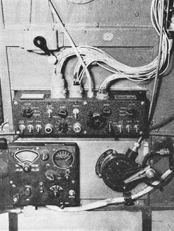
Fig. 5 - Bendix MS-106 control panel in modified Beechcraft
C-45.
The radio system controlled by this panel approaches in completeness those carried
by commercial airlines. And now that an outline of the problems to be answered has
been made let us get into the problems confronting the engineer from the actual
installation standpoint.
Transmitter Fixed Antennas
In low and high frequency transmitter work the problem of antennas will likely
remain as one of the greatest stumbling blocks to good transmitter efficiency. Due
to the small physical sizes of the medium weight aircraft in use a single, straight
wire of even thirty feet in length is difficult to obtain without many compromises.
For example, on one of the most widely used aircraft the distance from one vertical
fin to a mast located at a point above the cockpit is approximately twenty-two feet.
Twenty-two feet is less than one-third of a quarter wavelength for 3105 kilocycles.
The angle between the legs of a "V" formed by an antenna running from each vertical
fin to the mast above the cockpit is small. "Folding," and effective shortening
of the forty-four foot antenna obtained in this way, results. It is desirable, too,
to be able to use one fin-to-mast antenna for a range receiver without having to
employ an antenna changeover relay. If the communications antenna is used for a
range receiver such a relay is needed.
Unless the lead-in is made at some angle greater than sixty degrees to the straight
portion of the antenna the total electrical length is effectively shortened. In
this particular case a well spaced lead-in back through the fuselage to a point
just ahead of the horizontal stabilizer can be installed to allow the lead-in to
depart from the fuselage at close to a ninety degree angle (reducing capacity) and
feed the overhead portion of the communications antenna at close to a ninety degree
angle. Even though the lead-in is longer and inside the fuselage, an overall improvement
in effectiveness of the antenna can be obtained as compared with an antenna whose
lead-in within the fuselage is short, but which departs from the fuselage and feeds
the overhead portion of the antenna at comparatively sharp angles. Further improvement
in the characteristics may be obtained by carrying the overhead portion of the communications
antenna over the nose of the aircraft. A short mast, erected as far forward on the
nose as possible, is used to anchor the forward end of the communications antenna.
That is, of course, if the pilot's objection is not too great! By finishing such
a mast in dull black the reflection becomes nil, and actual obstruction to vision
is not nearly as much as would be thought.
The writer's experience has shown that an antenna such as just described "loads"
almost like a standard communications antenna on a Douglas DC-3, but of course,
the radiation is not nearly as good with equal power. In practice a fifty watt transmitter
working into an antenna with a nose mast gave coverage of at least 75 miles on the
congested itinerant frequency channel, 3105 kilocycles. "Clear channels" such as
used by commercial operators extend this range by several times. (See Fig. 3.)
On most of the smaller, single engined craft it is often necessary to depart
from a single wire and revert to the "clothes line" system of stringing wires from
wingtips to tail, etc. With high speed aircraft (over 180 miles per hour) many serious
disadvantages present themselves. It is entirely possible that mechanical resonance
between the aircraft structure and the antenna might occur. Vibration of the antenna
wire in the windstream could then cause antenna breakage, or structural failure.
It is obvious that a wire across the windstream will be more susceptible to icing
than one running lengthwise to the windstream and the ice load and shape will affect
the mechanical resonance point of the antenna. Angles of greater than 20° between
the antenna wire and windstream should not be exceeded where the airspeed is 180
miles per hour or over. Drag (wind resistance) increases rapidly, too, as the angle
increases.
The "spider web" type antenna system will certainly make possible transmitter
loading, yet the radiation resistance is usually rather low. It is also possible
that cancellation occurs to some degree.
The inconvenience to the loading of passengers who must thread their way through
a maze of wires has to be considered. In addition, greater difficulties and hazards
in hangaring an aircraft having such a web of wires hanging from it are encountered.
If damage is not done to another craft the antenna in question is often pulled loose,
stretched or otherwise made to require some maintenance.
Loading Units: Unless the transmitter itself has sufficient provision
for loading built into it some form of external loading unit will be required. A
very effective loading coil can be constructed with little cost. Loading coils should
be built of the lowest loss materials available and spaced as far away from any
structure as possible. A major disadvantage of external loading is that only one
frequency can be readily taken care of without resorting to a more or less complex
unit.
Antenna Icing, Precipitation and "Ground" Effects: No completely successful
simple method of combating ice and rain on antennas has been developed. Precipitation
of any kind seriously changes the antenna resistance and reduces radiation, usually
because of detuning. Wherever possible final tuning adjustments should be made in
flight in a clear sky to prevent the effects of ground capacity and precipitation.
The detuning experienced with the aircraft on the ground is not serious since contacts
with the control tower can still be made. Final tuning adjustments to transmitter
should never be made in rain or snow. Detuning due to precipitation of any kind
becomes more serious in its overall effect when the antenna resistance is small
since any change resulting from this source is a greater percentage of the total.
If transmitter tuning must be done in a hangar extreme care in prevention of fires
must be taken. It is definitely not a good practice. Nor can the adjustments be
considered final. An external primary power source should be used whenever possible
in order to save the low capacity aircraft batteries carried in the ship.
Trailing Wire Antennas: Trailing wire antennas are very often the only
answer to a highly efficient transmitter system. Unfortunately they are not only
inconvenient to the crew, causing additional work for them, but present actual danger
to those on the ground in case the antenna weight is lost while in flight or when
the antenna is not reeled when landing (forgetfulness on the pilot's part is not
always to blame!). A solid weight of any kind is unstable aerodynamically and will
oscillate especially as it is being reeled in. Damage to the aircraft structure
results if the weight strikes the ship. Unless the fairlead is properly located
the wire may foul some part of the landing gear, controls, pitot masts, etc. A piece
of one-inch open link chain weighing approximately a pound, although not good in
appearance (see Fig. 6), will not whip or oscillate. A string of lead beads
on a section of flexible cable is perfectly stable at all speeds. Neither of these
require a swivel to prevent twisting of the antenna wire as do any of the drag cup
or windsock type antenna "Drags." Rubber balls and windsocks are very popular with
small aircraft, but a strong swivel must be used even at the lower speeds if it
is to last very long.
The use of v.h.f. will make possible small, light and simple mast type antennas.
The lead-in problem and routing will be much simplified, too.
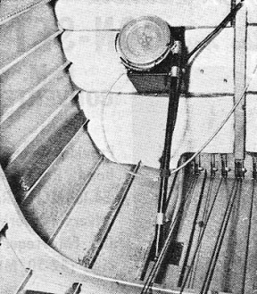
Fig. 6 - Trailing-wire antenna reel.
Antenna Changeover Relays: When a transmitter antenna is used for a
receiver antenna, a changeover switch must often be provided. The changeover relay
employed must be positive and not subject to vibration. Self cleaning contacts are
of primary importance and a cover of some kind should be used for protection from
dirt and damage. Intermittent and noisy receiver operation is often traced to this
source. Where high r.f. voltages must be handled, as is the case with a short antenna,
a vacuum relay may be required, and although they are more expensive their reliability
and trouble-free characteristics make them a good investment. Most transmitters
have built-in changeover relays, but the type of relay and its usage should be considered
nevertheless.
Receive?" Antennas: Balanced "T" antennas or balanced "V" antennas with
a vertical lead-in are preferred for receivers working on the 200 to 400 kilocycle
band due to more symmetrical "cone-of-silence" characteristics over the radio range
stations (nondirective reception). It is not always possible to attain this due
to mechanical mounting problems, etc., and fortunately, when a 75 megacycle marker
receiver is used the importance of the cone-of-silence indication is of less importance.
In addition better signal pickup is obtained with the same length of antenna used
as an "L" type rather than a "T" or "V" type antenna. A "T" or "V" antenna should
have at least eight feet on each leg for satisfactory service and be as well spaced
from the fuselage as possible. An "L" type approximately ten or twelve feet long
will prove adequate for most range receivers. The distortion of the cone-of-silence
due to directivity, is not often so serious as to make it useless in case the marker
receiver is not used.
Whip antennas have excellent characteristics, but there are two major objections
to their use. The first is their small size (approximately 5 1/2 to 6 feet) which
is not great enough for adequate signal pickup under all conditions. The second
is breakage. An "L" antenna for long distance work and a whip for close in radio
range work has been used with very good results. However, an antenna changeover
relay is required. Where possible the range receiver antenna should be located on
the belly of the aircraft in order to reduce to a minimum blanketing of the signal
by the aircraft and allow direct path reception. Small ground clearances and hazards
to ground crews will not always make belly mounting practical.
The ADF sense antenna will work most satisfactorily if it meets the requirements
as outlined above and at the same time passes directly over and in line with the
loop antenna. Minor departures from such installation have been made in many cases
which work perfectly. Automatic compass action is difficult to predict and ADF bearing
reversals may occur where extreme unbalance of loop sense antenna location exists.
An "L" antenna approximately ten feet in length passing over the loop housing with
four inches or more clearance will produce very good results.

Fig. 7 - Bendix MS-117 control panel mounted in a Beechcraft
Model 18.
Proper operation of the marker receiver is dependent to a large degree upon the
placement of the marker antenna with respect to all surrounding objects including
other antennas, landing gear, etc. The antenna should be horizontal in flying position
of the aircraft and the external lead-in short and vertical. A half wavelength or
approximately 76 inches is used. The position of the tap must be determined by the
spacing between the antenna and the aircraft structure. A fifty ohm coaxial line
is used for a lead-in inside the fuselage. The coaxial cable shielding must be grounded
directly at the point of entry of the external lead-in. Where the antenna has approximately
nine inches separation from the fuselage the tap is usually five to six inches off
center to produce the correct impedance matching. Adjacent antennas and obstructions
may cause severe distortion of the marker beacon patterns (due to marker antenna
directivity produced) to the extent that the marker station cannot be located accurately.
Audio signal will appear some time before the visual light signal. The visual light
signal should be visible for a period of approximately 20 to 25 seconds when passing
over a station at 3000 to 4000 feet at a speed of 120 miles per hour. Sensitivity
adjustments and antenna characteristics will determine the time element and in any
case the symmetry must be very good. Flight tests are the only means of determining
accurately the overall performance. Only high quality insulators should be used
on the marker antenna to reduce leakage and maintain the antenna characteristics
as nearly as possible to the original adjustments. A balanced "T" range receiver
antenna may sometimes also be used as marker receiver antenna by employing a coupling
transformer. Such a system may limit the size of the "T" antenna to a degree where
the range receiver is not as effective as is desired. Careful flight testing and
adjustment is needed. A half-wave dipole with the coaxial cable making connection
at the center of the antenna has been tried with some success, yet the mechanical
difficulties and maintenance required is almost prohibitive.
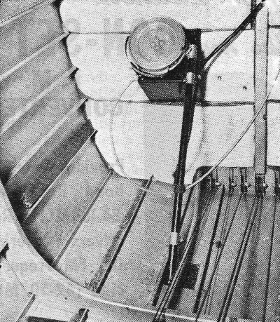
Loop Antennas: A preferred location for. an antistatic loop is on the
belly and free of obstructions. Difficulty of mounting, antenna cable length and
chances of mechanical damage sometimes dictate placement on the top-side. Practical
results have proven that loop antennas mounted on top give fully satisfactory results
operationally. If two loops are to be mounted adjacent to each other approximately
two feet of space should be allowed between them to prevent interaction or coupling.
This objection is not so serious where one is a fixed position loop.
In every case where a loop antenna is to be used to take bearings on a station,
calibration correction must be determined beforehand. Only in a very few instances
on wood constructed aircraft has calibration correction been so small as to be negligible.
On the other hand plus and minus errors of up to 20 degrees are common even where
the loop antenna is unobstructed and is placed symmetrically on the aircraft. Instructions
for calibration determination can be found in the manuals accompanying this type
of equipment, and although involved, is not particularly difficult.
Location of Radio Gear: Placement of the radio units poses several requirements,
each of which must be met. Four of the major considerations are as follows:
1. Available space. Standardization of unit size and multiples of this size have
been followed in the designs of the past few years in transport type equipment as
shown in Fig. 4. Most radio rack designs will accommodate them, however this
does not hold in all cases. A few aircraft are encountered in which radio racks
have not been installed and which require complete structures to be added. Modification
of existing racks, or addition of structure, must be approved by the Civil Aeronautics
Authority.
2. Structural strength. Often too little attention is paid to this phase. Radio
racks already installed have maximum load limits assigned. Where modification is
necessary, or new structure, careful structural strength investigation should be
made. A weight penalty results when the structure is heavier than needed and danger
of structural failure is present if too light. The radio rack itself is seldom part
of the primary airframe, but the tie-points are carefully chosen and reinforced
in order to properly distribute the load throughout the primary airframe structure.
Aircraft manufacturers go to great lengths to obtain adequate strength with light
weight. The airframes are normally designed to withstand loads as high as six or
more "G." Any changes or additions must be capable of withstanding similar loads
and yet not cause excess stresses to appear throughout the adjacent airframe. Civil
Air Regulations Bulletin No. 18 covers accepted practices and approved methods of
making repairs, materials used, rivet sizes, etc.
3. Location as regards antenna lead-ins; electrical cable routing; mechanical
shaft routing; accessibility for maintenance. In most cases considerable compromise
must be made in this category. Locating a unit in a compartment with a fuel tank,
even a well ventilated compartment, is highly dangerous since gasoline fumes are
almost always present after fueling and normal arcing of dynamotor brushes can cause
them to explode. Such installations have been made in exceptional cases but only
where the fuel tank compartment was perfectly sealed off from the radio or baggage
compartment in which the radio was located.
4. Weight and balance. This requirement becomes more critical as the weight of
the radio equipment increases in comparison with the total gross weight of the aircraft
since the percentage of change in c.g. (center of gravity) location is increased
and is, therefore, more pronounced. This is a straight-forward problem in mechanics.
Each aircraft has an individual operations record which includes the empty weight
of the craft, c.g. location and total empty weight moment (Weight in pounds multiplied
by moment arm in inches giving moment in inch-pounds).
The c.g. must lie within certain designated limits, fore and aft, (lateral c.g.
is not computed) in order for the aircraft to be licensed. In computing empty c.g,
expendable load such as fuel cannot be considered. However, fuel, oil, deicing fluid,
baggage, passengers and their locations must all be considered in the most unfavorable,
extreme positions in computing loaded weight. The c.g. must not exceed either the
forward or rearward limit under any condition of loading. In some cases a "placard"
is attached to the aircraft designating the allowable load, and its position. Such
limitation is very undesirable for the operator and should not result from the addition
of radio equipment if at all possible. In many cases a "loading schedule" is used.
Greater flexibility is obtained, but computation of load and its placement must
be made prior to a flight. Before an installation is begun careful investigation
should be made of the effect on c.g. location and the limitations that may be placed
on loading the aircraft. As was mentioned previously this becomes more critical
as the weight of the aircraft decreases.
The "reference" or "datum" line of the aircraft is usually the nose of the ship
in twin-engined craft; and the leading edge of the wing in single-engined craft.
Location of "items" are taken from this point which gives the "arm." The weight
of the item is then multiplied by the arm, resulting in the "moment." An algebraic
summation of the moments is added to the original moment shown in the operations
record. The total weight is added to the listed empty weight. The new c.g. can then
be obtained by dividing the new moment (inch-pounds) by the new empty weight (pounds).
The result is the new c.g. location (in inches) from the reference or datum line.
All items removed or added are handled in this manner and must be listed on the
operations record permanently. While anyone can make the computations they. must
be certified, and signed for, by a licensed aircraft mechanic.
In every case a licensed mechanic must supervise and approve all work done on
the aircraft and sign for its airworthiness, etc., in the aircraft's logbook and
operations record.
The quality of mechanical and electrical work done in aircraft is traditionally
high as compared to some other fields. It is the soundest investment an aircraft
owner can make - good work and maintenance. High standards should be expected and
demanded. A well made radio installation having good electrical connections well
supported cables, etc., will continue to give trouble-free, reliable service and
require little, if any, maintenance. A poorly made installation cannot be relied
upon and can eventually cost more than the original cost of the best.
Posted January 13, 2023
(updated from original
post on 12/8/2014)
|