A Portable Thyratron Tester |
||
The thyratron is not necessarily
a familiar type of vacuum tube to most RF and microwave electronics practitioners
unless they happen to be involved in radar, imaging (x-ray), particle accelerators,
etc.† It is basically a high speed, high current switch used in
pulse forming networks for firing magnetrons (via a high-voltage transformer). Both
the S-band airport surveillance radar and the X-band precision approach radar I
worked on in the USAF employed thyratrons. The X-band radar had been modified by
the time I came on the scene to use a solid state thyratron (one of the earliest
adaptations), but the S-band radar still used its original vacuum tube thyratron.
While I don't recall for certain, I
Being a lifelong electronics nerd and woodworker, I actually made a lamp out of a spent S-band thyratron tube (no photo, unfortunately). I turned an oak base on a lathe and then mounted the tube in the middle. Three 3/8" diameter brass tubes were bent to conform to the side of the vacuum tube and were joined with a brass strip at the top. A threaded lamp socket nipple went in the middle of the junction and the entire assembly was soldered. The bottoms of the tubes were epoxied into holes in the wood base spaced 120° apart around the tube's perimeter. The lamp cord was threaded through one of the brass tubes and routed out the side of the base to a plug. The bulb socket and harp for holding the shade topped off the lamp. My parents were the lucky recipients. While I regarded it as a fine example of artistic juxtaposing of classic wood and modern microwave electronics, they likely considered it as fitting for public display as Ralphie's mother did the "major award" his father won from an entry in a crossword puzzle contest which was the lady's fishnet-stockinged leg lamp (A Christmas Story). My lamp's current status is MIA - probably buried in the back yard like Mr. Paker's lamp. † RF Cafe visitor Jimmy C. pointed out another common use of the thyratron, "I would like to add Television Broadcast Transmitters using IOTs. The purpose of the thyratron is to remove the DC High Voltage from the IOT when there is an arc. The Thyratron actually shorts the high voltage to ground. Not sure how it handles 32,000 volts to ground but it does. It operates very fast. That is how it protects the IOT from damage." A Portable Thyratron Tester By W. Philbrook
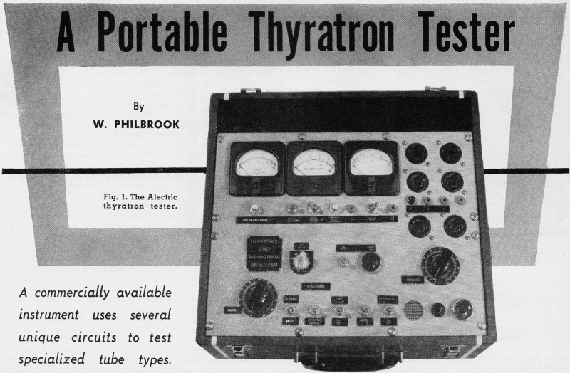
Figure 1 - The Alectric thyratron tester. A commercially available instrument uses several unique circuits to test specialized tube types. There are receiving tube checkers of almost every conceivable variety on the market but there has been no portable, easily usable tester for thyratron tubes. Why this condition has existed is difficult to say because, with the volume of industrial electronic equipment in current use, there should be an excellent sales potential for such a device. Now a tester has been developed which not only permits the rapid and accurate checking of a thyratron tube's characteristics, but does so with a number of unique circuits. Before we examine these circuits, it may be desirable to review the basic operation of a thyratron tube. Thyratrons are gas-filled tubes in which the flow of current is either at zero or at the saturation value. The grid voltage, usually negative, keeps them cut off until such time as it is desired to trigger them. At that time, the grid voltage is made relatively positive and electrons are thus permitted to flow from the cathode to the plate. Once this movement starts, even in a minute degree, the molecules of gas enclosed in the tube tend to become positively ionized. This condition of positive ionization neutralizes the holding or controlling voltage on the grid. This action completely opens the dam, so to speak, to the electrons being emitted by the cathode and permits current to surge freely through the tube to the plate. Once this flow has started, the grid loses all control over the rate of flow and - as long as the plate voltage is kept above a certain critical minimum - all electrons leaving the cathode travel to the plate. This, roughly, is how a thyratron tube operates. And to determine the operating condition of such a tube obviously requires a special type of tester. Let us therefore note the various thyratron features which are important and see how the tester shown in Fig. 1, made by the Alectric Mfg. Co. of Kenosha, Wis., accomplishes its testing function. One of the first things to observe is that most thyratrons operate with alternating voltage on the plate (or anode). This is done so that the grid may resume control of the tube after it has been fired or triggered. There is no point in having a tube in the circuit over which no control at all is possible, and the simplest way to achieve this control is to apply a.c. to the plate. When the plate voltage goes negative, conduction ceases, the ionized gas de-ionizes, and the control grid is able to prevent the flow of electrons from cathode to plate. The tube is now ready for the next triggering pulse.
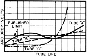
Figure 2 - Complete schematic for the Alectric specialized thyratron tester. Hence, if you examine the schematic diagram of this tester, Fig. 2, you will see that a.c. voltage is brought to the plate from one of two points: either the variable-voltage transformer, T1 or the step-up transformer, T3. Voltages from 0 to 200 volts are obtainable from T1 while 0 to 3000 volts (peak) can be obtained from the secondary of T3. The purpose of the low a.c. voltage is to check thyratrons at their rated currents - in this case, either 1, 2.5, or 6 amperes. By using a low voltage and proportionately low-valued resistors in the plate circuit, the wattage requirement and, with it, the heat dissipation can be kept within reasonable bounds. When checking 2.5 and 6 ampere tubes, even under these conditions, it is still necessary to place the plate load resistors in a separate box. If a higher plate voltage were used, the load resistances would be correspondingly higher and the wattage requirements would raise the cost of these units excessively. Hence, low plate voltages are used for certain tests where maximum rated anode currents are desired. On the other hand, when a thyratron tube is being checked for its grid-plate characteristics, we can use a high plate voltage and employ high-valued load resistances in the plate circuit to keep the current down. In this test, it is simply a question of establishing "trigger points" or critical grid voltages, not to determine what the peak plate current is. More on this test presently. The path of the a.c. voltage from T1 to the plate of the thyratron tube to be checked can be readily followed from Fig. 2. The start can be made at T1. From the center tap, point B, the line leads to switch S2, which for the purpose of this test is turned to the a.c. position. From S2, the path goes to point C, then through S2-4, which is now closed, to point D, then E, and finally through R7 to the plate of the thyratron. The other side of the circuit is completed from point A through S1-2, which is now closed, to F and from here to the center tap of the filament transformer, T5. Arc-Drop Test Now, as a measure of tube reliability, a direct measurement is not made of the tube's peak plate current. Rather we measure the voltage drop across the tube when the latter is conducting at full current. This voltage is known as the arc drop and its value is sought because an increase in the arc-drop voltage is the most outstanding indication of the end of life of a thyratron tube. However, a single arc-drop reading in itself will not indicate the life factor; rather what is needed is a series of readings over a period of time to anticipate the end. See Fig. 3. The technique could, in a way, be compared to the predicting of weather conditions by taking comparative readings on a barometer. It is suggested that a reading be taken after about every 400 hours of operation. As the arc-drop value begins to rise, a shorter interval should be observed - say every 200 hours as the tube approaches the end of its useful life.
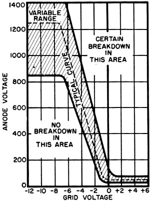
Figure 3 - The arc-drop voltage of a thyratron increases generally with the age of the tube, but may vary during life. It is an indication of tube condition. To be most effective, the arc-drop reading permits the end of life to be predicted so that the tube can be removed from operation before costly work stoppage occurs. A reasonable amount of arc-drop may well establish the limits at which such tubes should be removed to prevent emergency shut-downs. Once a tube is placed in operation, its arc-drop voltage will vary throughout its life. Typical variations are shown in Fig. 3. With tube "C" the rate of increase of the arc drop accelerates, but the curve is easily recognized. As a result, the tube can be replaced before this reading reaches its published limit. The steady linear rise with tube "B" is also easily recognized. As happens with some tubes, the limit is reached early with tube "A" but this condition is only temporary. The arc-drop voltage reduces below the limit again. However, the upward rise is soon resumed, so the tube should be changed the first time the limit is reached. When measuring the arc-drop voltage, simply placing an a.c. voltmeter across the tube would produce an erroneous indication. This is because on one half-cycle, when the tube is conducting, we would be measuring the true arc-drop value; however, on the other half-cycle, when the tube is non-conducting, the meter would be subject to the full applied a.c. voltage. The average of these two readings would be much higher than the true arc-drop value. In the Alectric tester, this difficulty is overcome by inserting the current coil of a wattmeter in series with the plate of the tube to be checked, while the voltage coil of the meter is placed across the tube, from plate to cathode. Since tube current flows only during one half-cycle, the wattmeter will be affected only during this period. During the subsequent negative half-cycle, no plate current flows, the current coil is inactive, and the meter is not actuated. Furthermore, the plate circuit resistance is so chosen that only 1 ampere flows through the current coil. This permits the meter scale to be calibrated directly in volts representing the arc-drop voltage. Additional switches (S3 and S4) and load resistors (R17 and R18) permit tubes with plate currents up to 6 amperes to be checked. (Although 6 amperes is the maximum current available, tubes through the 16-ampere rating are tested at the 6-ampere level.) Critical Anode Voltage Another characteristic of a thyratron is its critical anode starting voltage. This test is made at a specified control-grid voltage, usually on the order of 4 volts positive on the grid. The anode voltage, which is d.c. now, is slowly increased from zero until the firing point of the tube is reached. This value can be compared to that given by the manufacturer. Most of the time, the tube-data sheet will list the anode starting voltage for an average tube of a given type and also for the tube within the type with the highest starting voltage. The d.c. voltage required for this test is obtained from selenium rectifier SR1, resistor R4 and filter capacitor C1. For the test, S2 is placed in the d.c. position and the d.c. voltage developed across C1 is fed, via S1-4 to the anode of the thyratron tube to be tested. (S1-4 is closed for this test.) The voltmeter is placed in the position indicated by the dotted lines from the anode of the tube, through R37 and R16. Readings are taken on the low 100-volt scale, since the anode starting voltage seldom exceeds 50 or 60 volts when the control grid is 4 volts positive. The necessary positive grid voltage for the thyratron is obtained from the network consisting of T4 the two selenium rectifiers connected across T4 R26, C6 R25 and R24. The control grid is directly connected to the center tap of R24. The center arm of R-g; goes to the filament of the thyratron via a center tap on filament transformer T •. When the movable arm of R25, is exactly at its center position, there will be no difference of potential between the grid and filament. Turning the arm of R25 in one direction produces a nega\tive grid potential; rotating the arm in the opposite direction produces a positive grid voltage. This arrangement is simple and quite effective. Critical Grid Voltage To understand the purpose of the next test, that of determining the critical grid voltage, let us refer to a tube characteristic chart. This is shown in Fig. 4 for a C3J tube, but it is typical in form for a wide variety of thyratrons. In the section of the graph labeled "No Breakdown In This Area," no combination of certain a.c. anode voltages on the left-hand side with certain negative grid voltages shown at the bottom will cause the tube to fire. To reach the firing point of a tube, we must move into the shaded area. Some tubes may have to be driven deeper into this area (meaning either higher plate voltages or less negative grid voltages) before they are triggered, but they should fire before they reach the extreme right-hand edge of the shaded section. If this does not occur, some defect or variation from normal is indicated and the tube should be replaced. Beyond the shaded area and to the right of it, the control grid is generally so positive that almost any positive anode voltage will trigger the tube. Operation in this area is not sought because control of the tube is either difficult, variable, or impossible.
Figure 4 - Tube characteristic chart for the C3J, a typical thyratron, shows the range of combinations of grid and anode voltages that will cause firing, also the combinations of these voltages that will cause breakdown of the tube. To test a thyratron tube for its critical grid voltage, high-valued a.c. anode voltages are required. These are obtained from the secondary of transformer T3, where voltages having r.m.s. values to 1500 volts are available. In carrying out this test, S1-1 and S1-3 are closed, while S1-2 and S1-4 are open. Switch S2 is in the a.c. position. The voltage developed across the secondary winding of T3 reaches the plate of the test thyratron via R5 and R7. R5 is purposely made high in value so that the anode current will be kept below 40 ma. This is done because there is no desire to check the ability of the tube to produce its peak current; rather, all we wish to do is determine its critical grid voltage at a certain anode voltage. By keeping the current low, it is possible to use a low-wattage, inexpensive resistor for R5. We obtain the same value for the critical grid voltage whether a large or a small current flows after the tube has been triggered. Now to the test itself. It could be carried out by fixing the anode voltage at some value and then slowly reducing the negative grid voltage-making it more positive - until the tube fires. This would be done by slowly rotating R25 until the neon light in the plate circuit flickered on. However, the same characteristic can be determined automatically because of the presence of C3 and R38. Initially, R25 is set until it is 4 volts positive with respect to the filament. The a.c. anode voltage is then slowly increased until the tube fires. When this happens, the surge of current through the circuit charges C3, counteracting the initial +4 volts on the grid. During the next positive half-cycle of a.c. anode voltage, the tube firing point is governed by the combined voltage from R25 and C3. This combination, after a few cycles, attains an equilibrium level which is the critical grid voltage for that value of applied anode voltage. If we now change the anode voltage, by adjusting T1, then the total grid-to-filament voltage will reestablish itself at another equilibrium value which will represent the critical grid voltage for that anode voltage. For example, if the anode voltage is raised, the voltage across C3 will increase, effectively making the grid-to-filament potential more negative than it was before. Conversely, if the anode voltage is lowered, the average voltage developed across C3 will decrease. In essence, the network formed by C3, R38 , and R25 swings the tube's operating point a minute distance above and below the firing point. The range is governed by the values of these components (i.e., the overall time constant). Here it is chosen so that the meter needle recording the critical grid voltage remains quite steady as the anode voltage passes through its positive and negative half-cycles. Critical Grid Current The final characteristic of the tube to be checked is the critical grid current. This is the infinitesimal grid current that flows as the critical grid voltage is approached. It starts at the grid and flows down through R22 when push-button PB7 is opened. The voltage developed across R22 is negative on the grid side of the resistor and positive on the other side. Furthermore, this voltage adds to that provided by R25 and C3. To see how this critical current itself is measured, note first that R22 is a 1-megohm resistor. Since the critical grid current is in microamperes, the value of voltage developed across R22 is equal to the grid current in microamperes. When PB7 is closed, and the system is set up so that the critical grid voltage is indicated automatically, then the value of the total grid voltage is revealed by the grid voltmeter. This meter is connected between the bottom of R22 (and hence is not affected by any voltage that may develop across R22) and the center tap of the filament transformer. If, now, PB7 is opened, the critical grid current will flow through R22 and develop several volts here. This will alter the total grid-to-filament potential and drive the grid more negative. To bring the overall voltage back to the critical grid value point, the voltage across C3 will decrease by an amount equal to that brought into the circuit by R22. This change in C3 voltage will be reflected in the grid voltmeter reading since the latter, remember, measures both C3 voltage and that developed by R25. Thus, the change in reading on the grid voltmeter when PB7 is depressed represents the critical grid current in microamperes. This covers the operation of the tester in general and the tests it performs. Some odds and ends still remain, such as the VR-150 which is placed in parallel with C3. This tube serves to protect C3 when switch S8 is first opened and C3 is being charged initially. Voltage surges of a thousand volts or more frequently occur at this time. These would destroy C3 unless the latter had a sufficiently high breakdown voltage value. Since C3 possesses a high capacitance, using a unit with a high surge rating would be extremely costly. The difficulty is solved much more economically by having the VR-150 tube as protection. In the anode voltmeter circuit at the left, four ranges are obtained using only three push-buttons. With all buttons open, the voltmeter is on its 2000-volt range. For the 1000-volt range, the button so marked is depressed. The same is true for the 100- and 200-volt ranges; that is, the desired range is brought in by depressing the associated button. The circuit is so set up that, when either the 1000- or 2000-volt ranges are in use, depressing the 100- or 200-volt buttons accidentally will have no effect on the meter. This tester will also check phanotron tubes. These are tubes which are essentially thyratrons without a control grid. Hence, the tests are considerably simplified for them. Tests usually include arc-drop voltage, anode starting voltage, and an interelement short-circuit check. The prime purpose of any tube tester or analyzer is to permit a decision to be made on the condition of the tube. It is not a practical matter to construct a tester like the conventional radio-tube tester where a meter reads "good" or bad." In a thyratron, there are many factors other than the tube's ability to conduct a given quantity of current that determine its acceptance. That is why all of the foregoing tests are provided for and all should be performed if a true picture of condition is to be achieved.
Posted February 13, 2020 |
||