|
November 1957 Radio & TV News
 [Table
of Contents] [Table
of Contents]
Wax nostalgic about and learn from the history of early
electronics. See articles from
Radio & Television News, published 1919-1959. All copyrights hereby
acknowledged.
|
"The term, positive current
feedback, is disturbing to some because, as is well known, positive feedback increases
the distortion of an amplifier to which it is applied. This is true in this application
also, but it must be noted that the net feedback applied to the amplifier is never
positive but simply less negative in the region where the positive current feedback
is effective." Wow, that is a lot like what politicians refer to a
"baseline
budgeting." When one political party says it is going to "cut the budget," while
the other complains that doing so will "starve children" and "hurt women," what
it really means is that spending will not be increased this time as much as what
had originally been planned, although it will actually be higher than the last time.
We know the government never actually spends less money one year than it did the
year before, but there are a lot of "low information" people who never suspect a
thing - just keep the welfare checks and food stamps flowing.
A New Look at Positive Current Feedback
By H. D. Zink and L. R. Sanford
Tests show that positive current feedback improves hi-fi systems which already
have good loudspeakers providing the correct feedback circuit is employed.
 The use of current feedback to provide improved
bass response in a high-fidelity speaker system has caused a lot of discussion pro
and con. It has been argued that it cannot greatly improve speaker damping because
the mechanical parts of the speaker are not coupled closely enough to the electrical
parts.1 It has also been argued that it might help on an inadequate speaker
system but that it was worse than useless on a truly high-fidelity speaker.2
On the other side, curves have been presented which give dramatic proof of the improved
damping obtained with a particular kind of current feedback,3 but few
details are given about the speaker system used and, therefore, no adequate conclusions
can be drawn. This difference of opinion is understandable since the most desirable
mode of loudspeaker operation for the best listening is not agreed upon even by
experts in the field. The only way an individual can determine for himself the merits
of such feedback is by the use of his ears. The use of current feedback to provide improved
bass response in a high-fidelity speaker system has caused a lot of discussion pro
and con. It has been argued that it cannot greatly improve speaker damping because
the mechanical parts of the speaker are not coupled closely enough to the electrical
parts.1 It has also been argued that it might help on an inadequate speaker
system but that it was worse than useless on a truly high-fidelity speaker.2
On the other side, curves have been presented which give dramatic proof of the improved
damping obtained with a particular kind of current feedback,3 but few
details are given about the speaker system used and, therefore, no adequate conclusions
can be drawn. This difference of opinion is understandable since the most desirable
mode of loudspeaker operation for the best listening is not agreed upon even by
experts in the field. The only way an individual can determine for himself the merits
of such feedback is by the use of his ears.
Listening tests in commercial demonstration rooms are not necessarily conclusive
for two reasons; (1) many of the current feedback circuits are so arranged that
a common ground between the amplifier input and a speaker lead destroys the feedback
network and common grounds are frequently used in demonstration rooms, (2) many
amplifiers provide only for negative current feedback which can only decrease the
damping on a speaker and thereby accentuate its undesirable characteristics. Therefore,
opinions formed by a brief listening test in a demonstration room may not be valid
about current feedback.
The question in the minds of the authors was whether positive current feedback
(that which increases speaker damping) could add anything to a truly high-fidelity
system which already had good speakers. The results of tests showed the answer to
be conclusively yes, if the correct kind of feedback circuit were used. However,
the feedback configuration most suitable was different from those heretofore used
and for best results different speaker enclosures required somewhat different configurations.
What is actually accomplished with current feedback can be best understood by
forgetting the ideas of damping, negative impedance, etc. for the moment and concentrating
only on the frequency response. Anyone who has heard an audio oscillator through
any speaker system has probably observed that while the response may be poor below
a certain frequency, frequencies much lower than this can usually be reproduced
if the power to the speaker at these frequencies is increased relative to the higher
frequencies. Often, when this is done, appreciable harmonic distortion is present
and the speaker cone rattles. Usually for music system use, if the bass output from
the speaker is increased by conventional bass-boosting techniques, then such distortions
are objectionable. In the optimum use of positive current feedback these objections
to low-frequency boosting are overcome by using a rising bass characteristic as
part of the feedback network. This compensates for the loss of low-frequency acoustic
output without the harmful effect noted, since the positive current feedback keeps
the speaker cone under control and, thereby, significantly reduces the distortion
which would otherwise result.
In some cases, the frequency below which no acoustic output at all is obtained
is actually lowered.
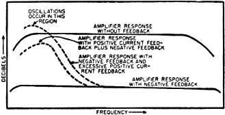
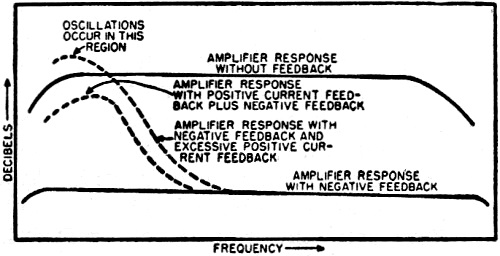
Fig. 1 - Effect of positive current feedback on the frequency
response of amplifier.
The term, positive current feedback, is disturbing to some because, as is well
known, positive feedback increases the distortion of an amplifier to which it is
applied. This is true in this application also, but it must be noted that the net
feedback applied to the amplifier is never positive but simply less negative in
the region where the positive current feedback is effective. See Fig. 1. The
slight increase in distortion, which results from the decrease in the amount of
negative feedback applied in the bass region, is more than offset by the decrease
in speaker distortion in the same region. In the high-frequency region, where amplifier
distortion is more disturbing, no positive feedback is applied and the amplifier
characteristics remain unchanged. The important point to note is that positive current
feedback applied to the amplifier is effectively negative feedback as far as the
speaker cone is concerned. This point is not obvious, so the following experiment
will be described to suggest why this is actually the case.
Arrange a speaker, battery, multi-range ammeter, and a switch as shown in Fig. 2.
With the switch on the "A" contacts so that the battery is out of the circuit, push
the speaker cone in the minus direction and note the direction of the current generated
by the movement of the voice coil through the speaker field. Assume this current
flows in the direction of the arrow I. Now connect the battery through the "B" contacts
so that the current which it causes to flow is also in the direction of the arrow,
and note the direction in which the speaker cone moves. It is found that the speaker
cone moves in the plus direction, that is, in the opposite direction from which
it was moved in the first case. The current which acts on the speaker results in
a plus motion of the cone whereas a minus motion of the cone produces the same direction
of current when the cone reacts on the circuit. This means that when the cone oscillates
after a driving signal has ceased, the current generated by the erroneous motion
can be fed back through the amplifier to produce a driving current which will be
in the same direction as the error current and that this current will drive the
cone in the opposite direction. The net effect will be that the cone moves very
little after the original driving force ceases. It can thus be seen that in order
for the forces on the cone to cancel out (negative feedback) the error signal must
be fed back without a change of phase (positive feedback).
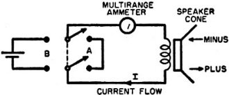
Fig. 2 - Experimental setup that is used to determine how
positive feedback works.
When these facts are realized, the correct application of positive current feedback
to any speaker system then becomes merely a matter of cut and try until the right
boost characteristic is found. Since no electrical measurements can indicate the
total effect, the final results must be reached by listening tests. The correct
results are achieved when the speaker has a deeper bass than it has ever reproduced
before - without any trace of boominess. A very good test is when low-level, low-frequency
bass notes, such as the light tap of a tympani, bass drum, or soft organ pedal,
are clearly evident without being boomy or muffled. An excellent demonstration of
the effect of positive current feedback was given when the low-frequency response
of a Klipschorn was extended from 27 cps to below 20 cps with a clean fundamental
response. The difference in reproduction of a complex 16 cps organ tone before and
after was quite impressive and easily noticed even by the untrained ear.
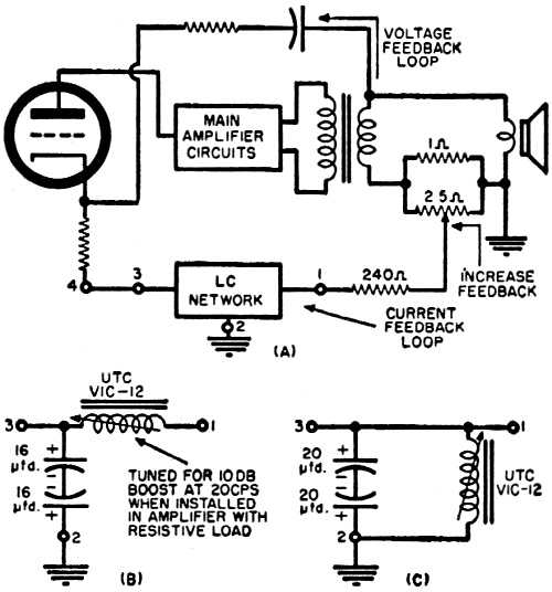
The block diagram of the current feedback network used by the authors is shown
in Fig. 3A. The essential difference between this circuit and similar ones
used on commercial amplifiers is that no provision is made for negative current
feedback, and an LC circuit is used in the frequency discriminating section of the
feedback network instead of a single capacitor. It is necessary to use an LC circuit
because the single capacitor gives too much bass boost in a region where no boost
is needed when used with some speaker systems (especially the Klipschorn and "Rebel"
series). This results in an unpleasant over-accentuated bass sound and is probably
the reason some have rejected the use of current feedback with high-quality speakers.
The 25-ohm potentiometer shunted across the 1-ohm resistor provides a means of
varying the feedback from zero to full positive. Its use, except tor comparison
purposes, is questionable since usually full positive feedback is the most desirable
condition. It could be omitted with no harmful effects in which case the 240-ohm
resistor is tied to the ungrounded end of the 1-ohm resistor.
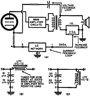
Fig. 3 - (A) Location of positive current feedback network.
(B) shows Klipschorn network. (C) shows Rebel 4 LC network.
The amount of feedback and therefore the degree of bass boost may be varied in
several ways aside from the use of the potentiometer. The principal way is by changing
the value of the 1-ohm resistor. It will be noted that a dividing network is formed
between the speaker impedance and the current feedback resistor, such that if the
speaker is high impedance (16 ohms) less feedback voltage will be developed across
the resistor than if the speaker impedance is low (4 ohms). That is, for a given
resistor more bass boost would be obtained when feeding a 4-ohm speaker than when
feeding a 16-ohm speaker. The 1-ohm resistor has been found satisfactory when used
with a speaker system having a net impedance of 4 ohms and, therefore, in some instances
a 4-ohm resistor might be desirable for a 16-ohm speaker system.
The amount of feedback and, therefore, the amount of boost can also be changed
by changing the "Q" of the circuit elements used in the feedback network. The values
called for usually require electrolytic capacitors and if these units are leaky
or are used singly instead of in series pairs back-to-back, then less feedback will
be obtained than would be expected. If the inductor used is variable, its "Q" will
vary as it is tuned and this will also change the feedback. It should be noted that
since the resistance in series with the speaker absorbs power it represents a loss
in peak output, therefore, it is desirable to keep it as small as possible while
still obtaining the required feedback voltage. Since high "Q" elements in the feedback
network represent more voltage feedback than do low "Q" ones, they are to be preferred
unless they give a boost characteristic that rises too sharply. This is an unlikely
occurrence. It should be noted that the characteristics of the network, when not
connected in the feedback loop, are not a good indication of the overall amplifier
response when the network is in the loop since a "Q" multiplication effect is obtained
and the amplifier response is sharper than the network response.
To determine the constants of the LC network shown in Fig. 3A, procure an
audio oscillator or frequency test record whose range is slightly lower than the
lowest range of interest and listen to the performance of the speaker system using
a conventional negative feedback amplifier. Note: (1) the frequency at which the
bass response just begins to roll off and (2) the frequency at which no more acoustic
output is obtained irrespective of how much power is used to drive the speaker.
An LC network having a low-pass or bandpass filter configuration is then designed
so that the upper turnover frequency occurs slightly above the frequency at which
the response starts to roll off and the peak response occurs slightly below the
frequency at which no output is normally heard. (The hypothetical termination resistance
necessary for calculating the filter sections can be assumed to be about 600 ohms
since it has been found experimentally that this value gives networks that are satisfactory.)
This network will serve as a starting point and by varying the parameters while
listening to the system using an audio oscillator or tone record the best sounding
arrangement can be determined. For those not technically able to perform such calculations,
the networks to be discussed will give moderately good results on any speaker system
and will serve as a starting point for more experimentation. It is not advisable
to use music for the first tests since low-frequency tones occur rather infrequently
and are of rather short duration so it is difficult to notice the effect of circuit
changes.
The specific LC circuit configuration used with a Klipschorn is shown in Fig. 3B.
This type of enclosure normally falls off below 27 cps so the feedback network is
designed to become effective in this region and to provide 10 db of boost at 20
cps as measured across a resistive load. The response curve of the amplifier, when
this circuit is used, is shown in Fig. 4A. It must be remembered that this
curve was taken with a 16-ohm resistive load substituted for the speaker and does
not necessarily represent the actual boost curve obtained with the speaker connected.
In this case, sufficient feedback is obtained from a 1-ohm resistor even though
the speaker is 16 ohms. Listening tests with an audio oscillator indicate that this
amplifier-speaker system appears to be acoustically flat to below 20 cps.

Fig. 4 - (A) Amplifier response with networks shown in Fig. 3B
and (B) Fig. 3C.
Fig. 3C shows the network found best for use with the Klipsch "Rebel 4"
enclosure. In the specific case considered here a G-E A1-400 speaker is used in
the "Rebel 4," but the same circuit is also used on a "Rebel 4" with a much cheaper
speaker and gives excellent results. The configuration is different from that used
with the Klipschorn because more boost is required and it was found that a network
that gave a steadily rising bass characteristic, such as used with the Klipschorn,
caused the amplifier to motorboat when the feedback was increased to the correct
point. This was because, when enough positive feedback was provided in the required
region, all of the negative feedback was cancelled out at some lower frequency and
the net amplifier feedback became positive in this region and caused the oscillation
(see Fig. 1). This condition is avoided with the configuration shown since
it is arranged to peak at the lowest usable frequency and then fall off below this
point so that the amplifier has almost full negative feedback in the critical motorboating
frequency range. This configuration also largely eliminates thumps that occur when
tuning through FM stations. Curves obtainable with this configuration are shown
in Fig. 4B and it must be noted that these curves also were taken with a resistive
load in place of the speaker. The solid curve was found most suitable in this case
and the low-frequency response of the "Rebel 4" enclosure with the G-E A1-400 speaker
was extended from 40 cps to slightly below 30 cps. It seemed as if several slight
peaks in the response were also eliminated.
An attempt has been made to explain positive current feedback from a different
viewpoint than is normally used and it is hoped that this article will clear up
some of the controversy surrounding the subject. Three high-fidelity systems have
been in use for almost one year with the networks described and at no time have
any unpleasant results been observed nor has any listening fatigue been felt. Using
these circuits on the Klipschorn and "Rebel" series enclosures gives a life-like
bass that is only equaled by the most elaborate systems that are available.
References
1. Crowhurst, N. H.: "What's All This About Damping," Audio, September, 1955
2. Klipsch, Paul: "Variable Damping," Radio-Electronics, October, 1956
3. Wilkins, Charles A.: "Variable Damping Factor Control," Audio, September,
1954
Posted January 5, 2023
(updated from original
post on 9/26/2014)
|