|
August 1947 Radio News
 [Table of Contents] [Table of Contents]
Wax nostalgic about and learn from the history of early
electronics. See articles from
Radio & Television News, published 1919-1959. All copyrights hereby
acknowledged.
|
This is the third and final installment
of a 1947 Radio News magazine series on iron core transformer and reactor
design. You of course are familiar with transformers, but what about reactors? A
reactor is an inductive element used to limit overvoltage or short
circuit current from a source to a load. These days they are most often seen in
electrical distribution substations, associated with transformers. I did not intend
to imply that you will learn something about reactors here; they were covered in
Part 1, "The design and construction of iron core transformers and reactors."
Part 2 is titled "Complete details for designing and constructing your own
iron core reactors." I will attempt to procure the June and July issues. In the
mean time, part 3 reviews the basics of transformer turns ratio and current transformation.
Practical Transformer Design and Construction
 By C. Roeschke By C. Roeschke
Part 3. Concluding article covering the design and construction of iron core
transformers and reactors.
In this final article on transformer design we will discuss the design and construction
of a plate modulation transformer, and an audio output transformer. Several valuable
hints on the practical construction of transformers are also included for the assistance
of the builder.
A modulation transformer, like any audio power transformer, is designed to match
the output impedance of one piece of equipment to an input impedance of a second
piece of equipment. This matching is done to insure maximum power transfer and satisfactory
frequency response.
When a load is connected to the secondary winding of an audio transformer, there
is reflected into the primary circuit an impedance which is determined by the turns
ratio of the transformer. This is the ratio of the number of turns in one winding
to the number of turns in the other winding.
Mathematically, the turns ratio is equal to the square root of the ratio of the
two impedances, or turns ratio = 
For example, consider a transformer which is to work out of a 5000 ohm circuit
into a load of 50 ohms. Then
Turns ratio = 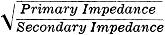 = =
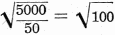 = 10. = 10.
This means that the primary winding must have ten times as many turns as the
secondary to match the 5000 ohm primary circuit to the 50 ohm secondary load.
For the purpose of design demonstration, assume that a plate modulation transformer
is required for the following conditions of operation.
1. Modulator output is push-pull pentodes requiring load impedance of 10,000
ohms and that each tube draws 60 ma. plate current.
2. Audio output power to be 7.5 watts.
3. The Class C r.f, amplifier to be plate modulated draws plate current of 70
ma. at 420 volts.
4. Voice frequencies are to be used. The secondary load resistance is equal to
the r.f. amplifier d.c. plate voltage divided by the r.f. amplifier plate current.
In this case then: R = 420/0.07 = 6000 ohms
To calculate turns ratio:
Turns ratio =  = 1.29 = 1.29
|
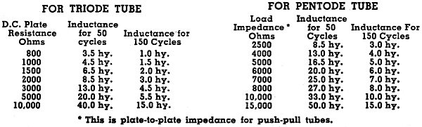
Fig. 16 - Primary inductance required for good response
at low frequencies. (hy. = henrys)
|
Therefore, the primary must have 1.29 times the number of turns used in the secondary.
When a transformer is employed in the plate circuit of a vacuum tube, it is necessary
that it be designed to reflect the proper load impedance for the tube. In addition,
the primary inductance will determine the low frequency response of that audio stage.
For this reason, Fig. 16 is included to indicate proper primary inductance
for good low frequency response at 50 cycles or 150 cycles. Fig. 9 ** can
be used to' calculate the primary inductance. Since our modulator tubes are pentodes
and we are interested only in voice frequencies, we see in Fig. 16 that the
primary inductance should be about 10 henrys.
Fig. 5* shows that the primary could be wound with No. 34 wire to carry
60 ma. and the secondary can be wound with No. 33 wire for 70 ma.
For convenience we shall use No. 33 . for both windings.
This transformer is to handle 7.5 watts so, according to Fig. 16, we can
try to design it with 1" laminations and a stack of 1".
Let us tabulate the data we have so far:
Primary impedance = 10,000 ohms Primary d.c. = 60 ma.
Primary inductance = 10 henrys
Primary wire size = No. 33
Secondary impedance = 6000 ohms
Secondary d.c. = 70 ma.
Secondary wire size = No. 33
Core size = 1" stack of 1" laminations
Turns ratio = 1.29
First let us try 2700 turns, center tapped, for the primary winding. Then the
secondary must have 2700/1.29 = 2090 turns. Next we calculate the coil size as explained
previously and find that the build is 81 per-cent which means that the coil will
fit into the core.
The primary is for push-pull tubes and therefore must be center tapped at 1350
turns. Since "B+" is connected to the center tap, the direct current flows in opposite
directions in each half of the winding which means that the core saturation effect
is cancelled out as far as the primary is concerned. But the secondary has 70 ma.
d.c. flowing through its entire length in one direction and this must be considered
in the calculation of inductance.
Then for the secondary, NI = 2090 x 0.07 = 146. But we are interested in the
primary inductance so let us convert this effect into the primary. Thus:
Since NI = 146
Then 2700 x I= 146
And I = 146/2700 = 0.054 amp.
This means that 54 ma. flowing in the 2700 turns primary would give the same
core saturation effect that 70 ma. flowing in the secondary would give. For this
reason we shall use the figure 54 ma. in our primary inductance calculation.
Then 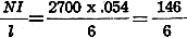 = 24.3 = 24.3
And from Fig. 9** if  = 24.3 then = 24.3 then
 = 0.5 x 10-2
= 0.005 = 0.5 x 10-2
= 0.005
By transposition if then L=
 (V = 6 cu. in.),or (V = 6 cu. in.),or
L =  = 10.3 henrys (primary
inductance). = 10.3 henrys (primary
inductance).
Therefore this design is satisfactory. In Fig. 12** we see that when NI/l
= 24.3 the paper gap in the core should be about 0.0015" thick.
Audio Output Transformer
Here let us assume that our audio amplifier employs the same output tubes as
used in the modulator described before, which means that the following conditions
exist:
Output tubes - P.P. pentodes (10,000 ohm load)
Plate Current - 60 ma. for each tube
Output Watts - 7.5
Lowest Frequency - 150 cycles (voice frequencies)
Required Primary Inductance - 10 henrys
Here we have the same primary circuit requirements which existed when we designed
the previous modulation transformer. Therefore, we can use the same core size and
primary winding.
Assume that at times this amplifier will feed into a 500 ohm line and that at
other times it will drive a loudspeaker having an 8 ohm voice coil. Then two secondary
windings will be needed; one for a 500 ohm load and one for an 8 ohm load.
Turns ratio = 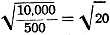 = 4.47 for 500 ohm winding,
and = 4.47 for 500 ohm winding,
and
 = 35.3 for 8 ohm winding. = 35.3 for 8 ohm winding.
With 2700 turns in the primary we find that the 500 ohm winding must have 2700/4.47
= 604 turns. Similarly, the 8 ohm winding must have 2700/35.3 = 76.5 turns (use
77 turns).
Now, we want to be able to put the full 7.5 watt output either into the 500 ohm
load or into the 8 ohm load. Then, the wire used in each of these secondary windings
must be heavy enough to carry such current. At 7.5 watts, the current in the 500
ohm winding is:
W = I2Z
Then: I2 = W/Z
And 
I = 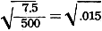 = 0.122 amp, or 122 ma. and the current
in the 8 ohm winding is: = 0.122 amp, or 122 ma. and the current
in the 8 ohm winding is:
I = 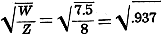 = 0.968 = 0.968
Fig. 5* indicates that the 500 ohm winding must be wound with No. 30 wire
to carry 0.122 amp and the 8 ohm winding must have at least a No. 22 wire to carry
0.968 amp.
The coil size calculation shows a build of 83 per-cent which is satisfactory.
Since the only direct current is in the primary winding where it flows in opposite
direction in each half of the coil, the core does not have to have a gap. The laminations
can be inter-leaved as in a power transformer core. Thus our design is a follows:
Core 1" iron 1" stack - laminations interleaved
Primary-2700 turns No. 33 wire, center tapped
500 ohm winding-604 turns No. 30 wire
8 ohm secondary-77 turns No. 22 wire
Only one secondary is to be used at one time.
Practical Hints
When the approximate specifications of a transformer are known, it is a simple
matter to determine its con-struction in more accurate detail.
*Figs. so designated appear in Part 1 of this article published in the June issue
of Radio News.
**Figs. so designated in Part 2 of this article published in the July issue or
Radio News.
Posted January 30, 2023
(updated from original
post on 10/13/2014)
|


