|
March 1957 Radio & Television News
 [Table
of Contents] [Table
of Contents]
Wax nostalgic about and learn from the history of early
electronics. See articles from
Radio & Television News, published 1919-1959. All copyrights hereby
acknowledged.
|
Multipath signal interference
is as prevalent today as it was at the beginning of radio communications - maybe
more so since there are typically more reflective obstacles between the transmitter
and the receiver. The evidence of multipath with digital communications, be it voice,
Internet page viewing, or movies, is slowness in transmission as opposed to the
analog case where garbled speech on radio and ghosting pictures on television are
the evidence. High data rates with digital transmissions typically mask the packet
errors and their necessary re-transmission; it all happens before the buffered information
is presented to the listener / viewer. However, there is no such buffering of over-the-air
radio or TV transmissions so evidence of multipath is immediately noticeable. I
remember how sometimes simply having a large metal trash or delivery truck roaming
through the neighborhood was enough to cause the Leave It to Beaver (and
other) program's pictures to lose sync. Now, as then, one of the best ways to mitigate
the issue is use of a directional antenna.
Problems in Metropolitan TV Reception
By Simon Holzman
Chief Antenna Engineer JFD Manufacturing Co., Inc.
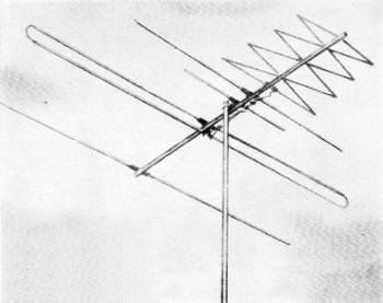
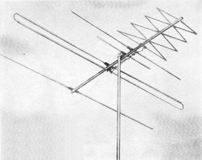
Fig. 1 - The JFD "Super Helix" is an example of an antenna
with a narrow polar angle (see Fig. 4B) that weakens ghosts.
Fringe areas have no monopoly on difficulties with picking up good signal. Overload,
ghosting, and interference often plague prime-signal locations.
While considerable attention has been given to the reception difficulties encountered
in areas distant from TV transmitting points, one sometimes forgets that television
installations in metropolitan and other primary areas often suffer from problems
peculiar to these locations. Noteworthy among these problems are those of ghosting,
graininess, the effects of too much (or too little) signal, cross-modulation, and
interference from a number of sources. In some cases, these conditions can be completely
controlled. In cases where they cannot be entirely eliminated, they may be greatly
minimized, as a rule, resulting in satisfactory reception.
In many localities, ghosting is a serious deterrent to acceptable viewing. This
phenomenon is caused by the simultaneous reception of out-of-phase signals on the
same channel. High-frequency TV waves are capable of being reradiated (as in radar)
by metallic bodies. The body reradiating these waves acts as a secondary transmitting
antenna and effectively "bounces" the signal in a different direction. The action
of two such reflecting bodies is illustrated in Fig. 3. Since the bounced
wave and the original signal travel different distances before arriving at the receiving
antenna, they are out-of-phase. The phase differential governs the degree of separation
of the two pictures on the screen.
To understand the cure, let us investigate two properties of receiving antennas.
The first of these, the front-to-back ratio, is the ratio of the received voltage
from the front of the array to the signal received from the rear, given equal power
densities in both cases. The higher the front-to-back ratio, the less signal the
antenna will receive from reflections coming in from in back of it.

Fig. 2 - Some interference can be tuned out with a receiver-installed
high "Q" frequency-selective adjustable trap.
The second property is the antenna's polar response. This has to do with the
directivity of the antenna with respect to a signal from one source. It is determined
by the angle formed between the direction or position in which the antenna is most
sensitive (forward pickup) and the direction or position in which it receives 3
db, or 30 percent, less signal from the same source. This may be measured by beaming
a constant signal toward the antenna while the latter is aimed directly at the transmitting
source, measuring the signal voltage generated in. the antenna, and then rotating
the antenna without changing the source until the antenna is in a position where
the signal generated in it is 3 db down.
In actual practice, this property is of interest because it describes the relative
sensitivity of the antenna to signals coming in from different directions. One signal,
for instance, may be an unwanted ghost. In Fig. 4 we see the effect of a wide
polar pattern (A) and a narrow one (B) in picking up or rejecting such a ghost.
In the former case, pickup of the ghost is almost as great as that of the primary
signal. In the latter case, the angle at which the ghost comes in is outside the
polar response angle, or 3-db point, and is sufficiently weaker so that its effect
on the viewed picture is considerably reduced. This property of an antenna is roughly
analogous to selectivity in the receiver's front end. An example of an antenna having
a small polar angle, the JFD "Super Helix", is shown in Fig. 1.
Unfortunately, narrow beamwidth goes hand in hand with high gain. Often, the
greater signal level, in a primary area, will overload the receiver causing buzz,
fuzziness, and tearing. This excess of signal, however, is easily compensated for
by the addition of an attenuator pad at the set terminals. This pad may have a fixed
value, but it is preferable to use a variable type since the degree of attenuation
required will vary with the location. Units of this type are readily available commercially.
The use of a pad will also help minimize ghosts, by bringing the level of the spurious
signal down to a non-visible value. Extreme caution must be exercised in an installation
of this type to orient the antenna accurately and to keep horizontal runs of lead-in
to a minimum. Horizontal lengths of twin-lead tend to act as signal-collecting devices,
and will complicate the original problem.
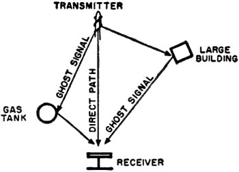
Fig. 3 - The longer paths of the reflected signals are responsible
for ghosts.
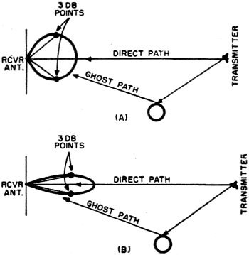
Fig. 4 - A narrow-beamed, more directional antenna, like
the one in (B), will reduce amplitude of the ghost.
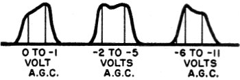
Fig. 5 - Receiver i.f. circuits are designed for best response
(center trace) over a certain normal range of a.g.c. voltage. Abnormally high signal
level (right) can deteriorate performance as much as low signal and a.g.c. values.
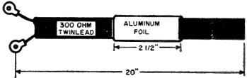
Fig. 6 - Tuned line is used to locate interference frequency
or act as trap.
In many metropolitan locations, extremely high signal levels are prevalent due
to the proximity of transmitting and receiving antennas and lack of blocking structures.
Too high a signal level can and does cause poor picture quality. The average television
set is aligned for maximum bandpass with an a.g.c. voltage of approximately minus
3 volts. As the signal increases, the a.g.c, level goes up, shifting the grid characteristics
of the r.f. and i.f. amplifier tubes that are controlled. When this occurs, each
of these tubes operates on a different portion of its curve, and its effective input
capacitance changes. This, in turn, causes deterioration of the bandpass characteristic
of the set, as shown in Fig. 5, and coarse, hazy pictures with poor definition
may result. There is also a tendency to poor synchronization due to pre-triggering
of the sweep oscillators. This condition may be eliminated by the same attenuator
pad mentioned previously. The pad should be adjusted for a barely sufficient signal
on the weakest channel. If some channels are still overloaded, a switch type pad
should be used, so that it may be switched into the antenna system only on those
channels where it is needed.
Cross-modulation, or windshield wiper, is another symptom of too much signal.
It usually manifests itself as a dark vertical bar sweeping horizontally back and
forth through the picture. This particular trouble is usually caused by a single
channel much stronger than the others. TV tuners are rarely selective enough to
eliminate this annoying feature particularly on channels adjacent to overly strong
ones.
If all channels are sufficiently powerful, an attenuator pad may be used to reduce
the overall signal level. A preferable method, however, is to install an adjustable
high-"Q" trap in the lead-in, and set it for sufficient attenuation of the undesired
channel. This is the equivalent of a frequency-selective attenuator. These adjustments
are usually quite critical, and care should be taken when they are made. The interfering
channel can be identified by turning the channel selector to the unused channel
positions, and noting which channel is most often seen. A commercial version of
such an attenuator that may be adjusted for rejection on the high v.h.f. band is
shown in Fig. 2.
In an urban area, there are many sources of interference. Interference caused
by amateur radio transmitters is usually of a frequency below 50 megacycles. This,
as a rule, can be eliminated by the use of a high-pass filter. This type of filter
should be installed as close to the set's antenna terminals as possible, so that
there will not be pickup of interference along the lead-in wire beyond the filter.
The previously mentioned selective high-"Q" traps will be of great use in removing
interference caused by powerful local FM transmitters.
Pulse-type interference, one form of which is ignition noise is often the most
difficult type to eliminate. In its milder forms, putting a tight twist in the downlead
may be sufficient to minimize it. Care should be taken in the original installation
to keep the antenna and lead-in as far as possible from sources of ignition noise.
Grounded metal screening, used to shield the antenna from the street or other source
of ignition noise, is often used with considerable success.
In exceptionally noisy areas, shielded 300-ohm twin-lead or coaxial cable should
be used. The outer shield should be grounded at as many points as possible. When
using 75-ohm coaxial cable, a balun impedance transformer must be installed at the
top to match the antenna to the characteristic impedance of the line. Another transformer
must be used at the set to match the line to the balanced 300-ohm input of the front
end.
Both shielded 300-ohm cable and coaxial cable have comparatively high signal
loss. For this reason, a moderately high-gain antenna may be needed to compensate
for these line losses.
It is often difficult to determine the source and frequency of an interfering
signal. A convenient gimmick that the technician can carry with him is a 20-inch
length of 300-ohm twin-lead, with lugs attached to one end and the other end cut
straight across and left open-circuited. A piece of aluminum foil should be wrapped
around the twin-lead for a length of about 2 1/2 inches, as shown in Fig. 6.
This forms a capacitively loaded half-wave line. In use, the lugs are attached to
the antenna terminals of the set in parallel with the antenna lead-in, which remains
connected. The interference is then tuned in, and the foil moved up and down the
line until a point is found at which the interference is at a minimum.
Diathermy interference is rare today, but, when present, is extremely annoying.
The best cure for this condition is to locate the source and notify the Federal
Communications Commission. For several years, it has been illegal for a diathermy
machine to radiate and cause interference.
Most cases of insufficient signal in metropolitan areas are caused by blocking
of the direct signal by a tall structure, such as an apartment house. In cases such
as this, reception may often be obtained by means of a high-gain, sharply directional
antenna, an example of which has been shown, oriented to receive a bounced signal
from some large structure to the side or rear. When this means is ineffective, an
attempt should be made to get permission to install the antenna on the roof of the
structure that is blocking the signal. A third alternative is the use of a tower
or telescopic mast, enabling the antenna to be even with or above the edge of the
roof of the blocking structure. A 30-foot height will usually be more than suf-ficient.
Reception problems caused by the use of indoor antennas are difficult, if not
impossible, to solve. Generally, the best cure is an outdoor roof installation.
A final difficulty occasionally observed is phase shift due to high voltage standing-wave
ratio. The phase shift manifests itself as a ghost which will change position with
variations in the fine tuning adjustment. This is almost always due to faulty installation
techniques. Be sure the lead-in has minimal horizontal runs and does not run parallel
to metallic objects closer than 6 inches. Often, the condition can be eliminated
by removing several inches of lead-in from the slack left behind the set. This slack
should also be kept as short as possible.
Posted February 12, 2020
(updated from original post on 2/17/2014)
|