|
If the history of radar intrigues
you, then you will not want to miss this article titled "Radar: The Silent
Weapon of World War 2," from the October 1945 edition of Radio News
magazine. There are a couple dozen photos of early radar equipment installations
on land, ships, and aircraft. Radar pioneers Dr. A. Hoyt Taylor, Chief Consultant
and Chief Coordinator of Electronics at Naval Research Laboratory, and Leo C. Young
are pictured reminiscing over the "scope" of radar's history beside the first radar
set at the Research Laboratory. In 1922, while experimenting with communications
equipment for the Navy, the two men made the initial discovery of distortion in
radio reception caused by the intrusion of objects between the transmitter and receiver.
Working from this discovery, they and a number of associates made great strides
forward into the vast sphere of scientific fields covered by the word "radar"
today. Do you see the name(s) of anyone you know?
Thanks to Terry W. for providing this article.
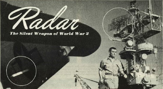
Radar: The Silent Weapon of World War 2
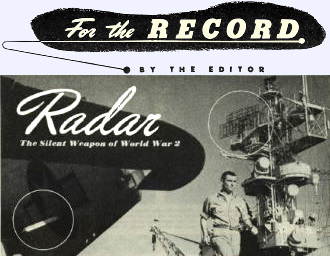 The trellis-work of this
ship's radar, outlined against the sky, is in contrast to the small antenna
on the wing of the General Motors Avenger torpedo bomber shown in foreground. Close
inspection at this plane installation will reveal the "teeth" of the antenna
affixed to the terminal of the white strut. This installation is a Yagi type antenna.
The vessel is a Navy escort aircraft carrier, photographed while at sea.
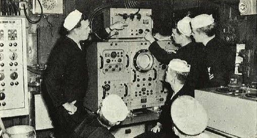
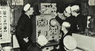
 Enlisted men in a radar unit listen to instruction during shakedown
cruise of a Navy warship. Instructors are also enlisted men chosen for their aptitude
and actual experience. Enlisted men in a radar unit listen to instruction during shakedown
cruise of a Navy warship. Instructors are also enlisted men chosen for their aptitude
and actual experience.
An electronic "eye" apparently developed independently by U.S., British,
French, and German scientists in the 1930s, radar owes much of its rapid growth
to the advent of war. First used in detection of surface objects in the near-distance
under conditions of poor visibility, radar's range and versatility were quickly
extended to provide long-range detection of air-borne, as well as surface objects,
accuracy in fire-control, and identification of distant or unrecognizable planes
and ships. To radar, the silent weapon of World War 2, goes much of the credit for
England's doughty defense in the dark days of the "blitz", and also
for "lighting the way" for our victories in the Pacific.
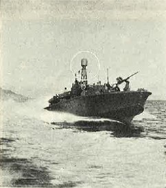
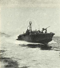
Thinking cap" of the PT boats, the "radome" bulb,
shown circled, houses the antenna of the radar set aboard the vessel Invaluable
to the hard-hitting PTs, because of their habitual tendency to operate under the
cover of night, radar's electronic eye pierces the darkness. indicating the
various targets and warning of immediate navigational dangers.
|
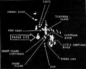
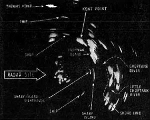
Radar equipment at the Naval Research Laboratory, Chesapeake
Bay Annex, recently made this "search" of surrounding terrain. Lettered
on the photographs of the PPI (Plan Position Indicator) scope are designations of
points picked up by radar pulse. Compare the photograph (left) made with a considerably
larger range with the photograph (right) made with a substantially lesser range,
both of which represent scope of the same area. Notice how "pips" converge
when the range is widened and diverge when the range is lessened.
|
|
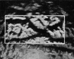 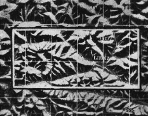
Radar takes a lot of the woe out of mountain flying. A navigator
equipped with relief maps and scope pictures can determine his position without
any trouble al any hour of the day or night. as the radar scope will show a pattern
almost identical with his maps. Above photographs show scope picture (left) compared
to same section on relief map (right).
|
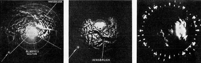 |
| (Left, Center) Radar's directional characteristics
are such that its results can be minimized by contour of terrain below. These two
pictures of Innsbruck. Austria. illustrate what directional approach can do. Picture
at left made on approach from south. shows city. Picture at right made on approach
from north. spots general contour of valley. but fails to show the city proper.
(Right) This photograph of a ship's PPI (Plan Position Indicator) scope was
taken during the invasion of Lingayen on Luzon. The cluster of white dots shown
in the photograph represents warships in the bombardment group: the large white
mass. the coast. headlands. and highlands of the island: behind the attack flotilla.
transports and the other ships composing the large invasion armada throw light pips
on the radar scope. |
|
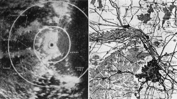
P·38 radar reconnaissance missions provide scope photographs
for routes to and from the targets, as well as series of target runs, made from
the cardinal points of the compass and from the logical axes of attack. The scope
photographs made by reconnaissance planes are plotted on maps and reproduced for
reference by Pathfinder operators during the actual bombing missions. In the photograph
at left. forest areas around Vienna. Austria are resolved on scope in droopsnoot
P-38. Returns are good enough to be used as check points in radar navigation. Map
at right covers same area as shown on scope."
|
|
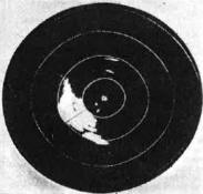
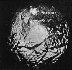
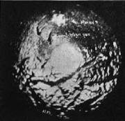
Scope picture" of Oahu in the Hawaiian Islands made by a Navy plane on a
radar test. Blob of light in center of the photograph marks the position of plane
as shown on indicator of its radar: the island itself is the largest white area
with low points in the topography in black. The two "pips" between the
inner and second circles are ships.
|
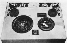
Radar repeater unit which repeats information from main
SG type radar so operator in remote position may have indication exactly the same
as main unit. Units of this type enable several positions to simultaneously monitor
main radar unit. thus eliminating much delay in transmitting Information to all
locations at one time and affording multiple checks.
|
Radar photography experts consider this picture one of
the best of its type. It was taken over the Munich area. with Munich proper shown
as the light spot at the top.
|
|
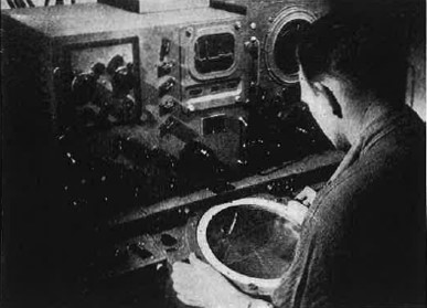
Operator using a type SG radar indicator to obtain the range
and bearing of target, The relative bearing of operator's ship may be seen in
center, just to the left of scope. Equipment of this nature is also used for plotting
position of ship.
|
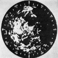
Close-up of a typical pattern as seen on an SG radar scope. A
picture such as this affords the operator a complete picture of the territory in
all directions from the ship in spite of the log or darkness, and may be quite readily
compared with ordinary, conventional maps.
|
|
Study in black and white-radar training at a naval air station in U.S. Officers
and men spend long hours. that will later pay dividends, studying intricacies of
the "electronic eye" in simulated plot room.
|
A typical parabolic antenna used with many types of radar equipment. By employing
a parabolic antenna, very high gain and a highly directional beam are obtained.
|
|
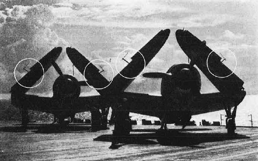
The slim and angular "elbows" of radar antennas are
silhouetted atop folded wings of these Curtiss Helldivers spotted on flight deck
of a Navy Essex-class carrier somewhere at sea. Adding this equipment to Navy planes
gave the effect of applying telescopes to the "eyes of the Fleet" as aircraft
are often known.
|
|

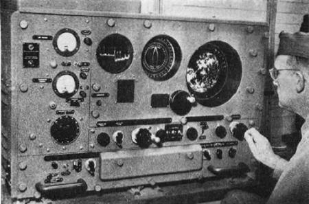
Through the electronic eye of radar. a Navy man determines distance
and bearing of his "target" during experiments at the Naval Air Station,
Anacostia. D.C. The indicator bearing the graph-like line in the center of the equipment
is an A-scope; the large disc into which he is peering s a PPI scope - Plan Position
Indicator.

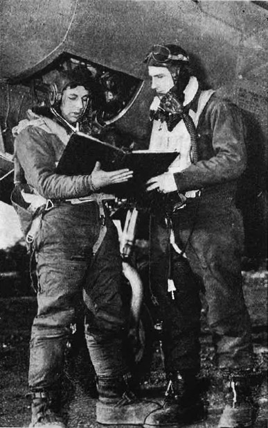
Radar equipped P-38 "Lightning" reconnaissance plane,
its "droop snoot" nose crammed with special electronic devices. readies
for a take-off. Trips like these precede visits of giant bombers against enemy industrial
targets. Intensive preliminary planning characterizes reconnaissance trips of this
nature since the plane carries no armament and is under orders to avoid combat.
Pilot and radar operator agree on final details of flight plan which will be followed.
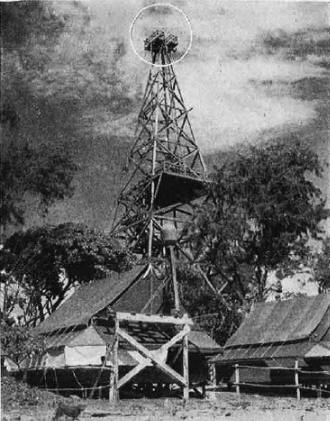
Instruction and improvements in radar are constant necessities
in the Navy. At this station on Espiritu Santo, two types of radar antennas can
be seen - one housed in a radome near the ground, the other installed on a towering "mast"
By their use, Navy men on duty instruct or get instruction on latest in radar operations.
|
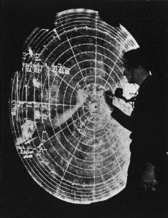
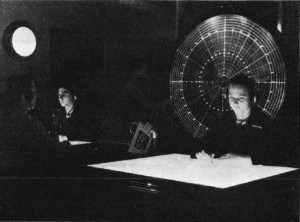
Information provided by radar's electronic eye is marked
down on a vertical chart in the radar plot room of an Essex-class carrier during
strikes against the Japs early in 1945. Behind the transparent expanse of the giant
circle other enlisted men can be seen working on various additional aspects of the
incoming flow of information.
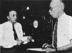
Pioneer workers in radar, Dr. A. Hoyt Taylor (right), Chief Consultant
and Chief Coordinator of Electronics at Naval Research Laboratory, Anacostia, D.C.,
and his long-time associate, Leo C. Young reminisce over the "scope" of
radar's history beside the first radar set at the Research Laboratory. Few men
know the history better. In 1922, while experimenting with communications equipment
for the Navy, they made the initial discovery of distortion in radio reception caused
by the intrusion of objects between transmitter and receiver. Working from this
discovery, the two men and a number of associates and assistants made giant strides
forward into the vast sphere of scientific fields covered by the word "radar"
today. The equipment in the background, crude and elementary in comparison with
the sets of today, was a breathtaking innovation when first used in 1937.
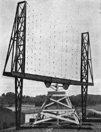
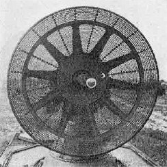
Close-up of the antenna of the first complete radar, installed "topside"
of a building at Naval Research Laboratory in Anacostia, D.C., in the late 1930s.
It is a "dirigible" antenna, meaning it is so mounted that it can be turned
to allow for around the compass search. See photograph lower right for below-decks
equipment.
|
|
Photograph of the first radar installation on a ship. Shown in
the upper right-hand comer is a Yagi-type antenna mounted to a five-inch gun on
the old USS Leary in 1937. The antenna was swung about by moving the gun. The photograph
was taken during epochal tests in Chesapeake Bay, when equipment marked a monumental
milestone in radar's history.
|
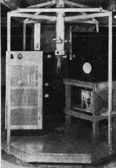
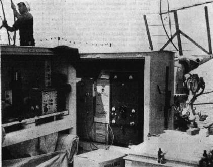
Below-decks view of the first complete radar set. The "dirigible"
mast in the very center of the photograph pierces the ceiling and its upper extension
bears the mattress antenna of the radar. Thus the operator below can turn the mast
to cover the compass while making a search. The antenna can also be tilted. with
the handle visible on the side of the mast. This equipment was so heavy, compared
to present sets. that in order to tilt and turn it, two men had to do the job.
|
Posted May 15, 2023
(updated from original post
on 4/13/2013)
|