|
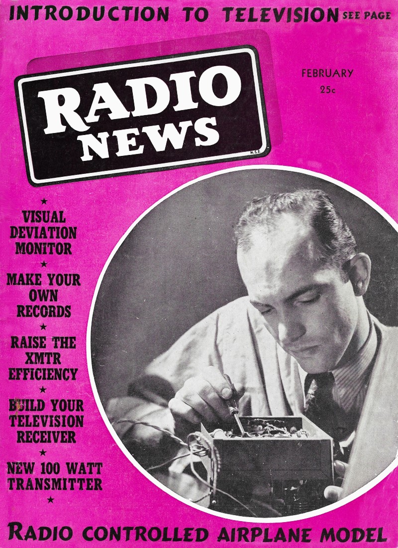
February 1939 Radio News
 [Table of Contents] [Table of Contents]
Wax nostalgic about and learn from the history of early
electronics. See articles from
Radio & Television News, published 1919-1959. All copyrights hereby
acknowledged.
|
Most people familiar with
the history of radio control (R/C) airplanes credit twin brothers
Walt and
Bill Good for the first truly successful
R/C airplane,
which they dubbed "Big Guff," in 1938. Interestingly, this
YouTube interview with the Good brothers
mentions, as does Mr. Isberg in his 1939 article in Radio News
magazine article, the first sanctioned R/C contest where the Good's model was
the only one to fly. Ross Hull and Clinton DeSoto were two other prominent early
R/C'ers. Transmitter operators were licensed Hams who designed and built their
own equipment at 56 MHz, unlike modern turn-key R/C systems operating in
unlicensed ISM bands. Vacuum tubes were used in the transmitter and the airborne
receiver. Lead-acid batteries often provided power for the receiver and control
surface actuators (pseudo-servos) in the airplane, which unfortunately would
burst during a crash (a frequent form of "landing," unfortunately, in the early
times) and compromise an otherwise salvageable wreck. The transmitter was so
heavy that that electronics and batteries sat on the ground while only a cable-connected
control box was held by the pilot. Airplane models were necessarily large in
order to lift the weight of the electronics, batteries, and servomotors (of
sorts). As usual, those early pioneers took the figurative arrows for those
of us who followed in their footsteps, who now enjoy the convenience of reliable,
highly functional, light weight, relatively inexpensive radio control systems
today.
See also Radio
Controlled Flight.
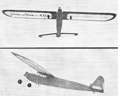
A Radio Controlled Model Airplane
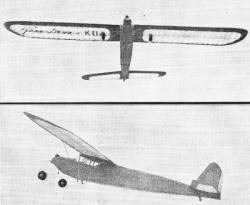
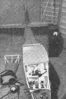
Two views taken of the model in actual radio-controlled
flight.
By R. A. Isberg
Engineer, Station KOA
Denver, Colorado
The author gives the first complete, comprehensive study on the radio control
of model aircraft with all diagrams on how to build your own.
Indescribable thrills are in store for the pilot of a model plane whose maneuvers
can be directed by radio. Mastery of two highly specialized sciences is requisite,
each with its own absorbing problems and the combination presents exceptional
opportunities for individual and group achievement, something which is rapidly
disappearing in the ham game as a result of the general adoption of manufactured
receivers and transmitters.
A radio amateur need not necessarily take up the building of model airplanes
in order to have a part in the fun. In fact, that would hardly be advisable:
because he would probably slight the airplane in order to better accommodate
the radio equipment; likewise, the model builder is poorly prepared to add radio
control to his plane. The ideal arrangement, (if you are not already a dyed
in the wool ham and aviator combined) is to find someone in your locality who
understands model aircraft construction and then form a partnership.
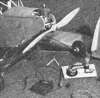
Radio control equipment mounted in the model plane ready
for the takeoff.
This is not difficult because there are model clubs in practically every
town. If you don't know any of the modelers in your community, write to the
National Aeronautics Assn., Washington, D. C. (every owner of a gas model is
registered) for addresses or shop around the department stores until you find
a clerk behind a counter full of model accessories. Another advantage of working
with someone else - the expenses are shared and if the experiment ends with
a disastrous crackup you will have someone to console - and to console you.
Radio direction of models is by no means a new field, - it really started
with radio communication; however, the bulk of the equipment necessary plus
the unreliability of its operation retarded development and interested only
a few advanced amateurs who specialized in model boats. The method most used
until recent years utilized a spark transmitter (which is illegal) to send impulses
to a coherer type receiver. Naturally, the range of operation was very limited
and the results uncertain.
As far as the majority of amateurs and model builders were concerned there
were other more interesting things to do and with the exception of an occasional
flicker of activity, thoughts of radio control were only day dreams.
An announcement of a radio controlled model airplane competition at the Detroit
meet in 1937, started the first general wave of enthusiasm. Six modelers displayed
ships and control systems, but only one ship, built by Chester Lanzo,1
flew. His control system (for direction only) consisted of a three tube regenerative
receiver operating on 80 meters, a homemade sensitive relay, and a small 1 1/2
volt locomotive motor with a gear train to operate the rudder. The controls
were demonstrated to be opera table by signals from an amateur station several
hundred miles away. His plane weighed five and three-quarter pounds including
the one and three-quarters pound receiver and control mechanism. A one-fifth
horsepower gas engine powered the ship and I understand it was usually hand
launched because this was not quite enough power for the weight of the plane.
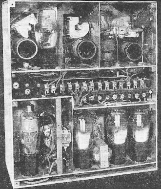
The control receiver removed from the plane to show its
construction.
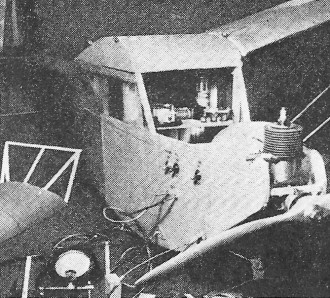
All test points and switches are mounted externally for
simplicity.
The late Ross Hull developed a system2 for controlling sail planes
during the same summer. His receiver consisted of a type 30 self-quenched super-regenerative
detector, a 1B5 first audio and a 1F4 second audio stage. An Eby sensitive relay
in the output circuit was used to control a solenoid which operated a simple
rubber powered escapement permitting selection of right, neutral, left and neutral
rudder positions. This scheme is very practical because the "pilot" on the ground
knows exactly what position the rudder is in and how many impulses are required
to turn it to a desired position. A system not using an escapement, such as
a motor driven gear box without stops, is likely to bring about a crackup due
to poor coordination between the pilot and plane.
While the 1938 entries in the Detroit competition were more advanced and
were probably capable of more satisfactory operation than those of 1937, none
of them could be demonstrated in the actual competition. The winning ship, Walter
Good's, cracked up just after taking off and no other entries were flown due
to the uncertain wind conditions. Good's plane was equipped with two radio channels,
using two one tube (type 30) receivers of the type shown in Figure 3. His control
system operated both rudder tab and elevators by means of Sigma relays and home
made electromagnetic escapements.3 Second place was awarded Clinton
B. DeSoto on merit.
The plane used in our experiments was designed and built by Robert Van Buskirk
of Denver who has been active in local and national model competition. The plane
has a twelve foot wing spread and a seven foot fuselage. It is powered by a
1/3 hp. Forester gas engine and it weighs about twelve pounds complete with
all radio equipment, batteries, and fuel. It has sufficient power to take off
and climb steadily provided there is not a strong wind.
Our control has been used for direction only because we wanted thoroughly
to master turning the ship before we tried diving or zooming. It is easy enough
to washout the experiment if there is only one control to manipulate; particularly
if the ship turns across a gusty wind when it is only a few feet off the ground.
Control of direction is more valuable and necessary than control of elevation.
It is most important to keep the plane within vision and to make it land on
the field from which it took off; not to mention the fun you can have turning
it to the right or left and describing figure eights in the sky.
Four receivers have been used in our plane. The first was patterned after
the receiver Ross Hull described for use in sail planes. It was found to be
impractical for powered ships because its output was too low to operate the
relay satisfactorily when the contacts and tension spring were adjusted for
minimum effect of motor vibration. The receiver operated on pulses of carrier
which would stop the super-regenerative hiss of the detector which in turn caused
the bias on the grid of the second audio tube to be substantially reduced, causing
a change from .6 to 2 ma. in plate current. The idling current of 0.6 ma. in
plate circuit magnetized the core of the Eby relay enough to make tension adjustments
difficult and the additional 1.4 ma. plate current (when a pulse of carrier
was transmitted) was not quite enough to close the contacts when they were adjusted
for minimum effect of motor vibration.
After taking stock of the situation we decided there must be some other way
which would eliminate the relay and its troubles and at the same time reduce
the weight of the receiver. A tuned reed system was decided upon because it
would permit selective right or left direction and would not be influenced by
a frequency other than the resonant frequency of the reed. After considerable
effort a reed system which would operate on one milliwatt was built. It worked
very well as long as it was fed a pure tone from a good audio oscillator, but
distortion of the transmitted wave form on the low frequencies (30-70 cycles
which were found optimum for transmitting power to the motor) caused us to abandon
the reed experiment.
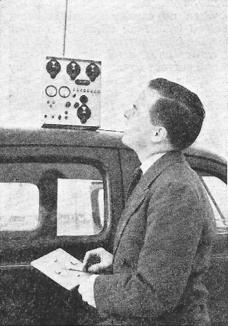
The control end of the flight. A 5 meter transmitter was
used.

The take-off must be made into the wind, before radio can
help.
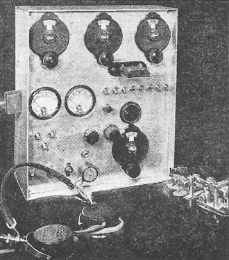
Radio control was by an ordinary ham transmitter.
The rear of the ground control rig.
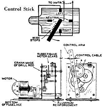
Control stick and control motor construction.
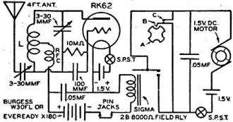
One tube control circuit.

Three tube control circuit.
Those of you who have worked with audio amplifiers on low frequencies will
appreciate that distortion of wave form is more apparent and amplifier efficiency
falls off rapidly below 100 cycles unless special design features and components
are used. The added complications and increased weight of the receiver, let
alone the construction of a high quality modulator and accurate tone generators
made it impractical. However, we learned that reeds can be operated on low power,
and we know that, fundamentally, a reed system can be made to work.
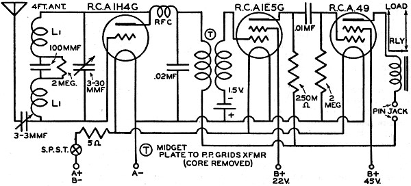
Our next receiver, and the first successful one, was an improvement on the
Hull receiver. It used a 1H4G detector, 1E5G second audio, and a 49 in the last
audio stage with a 5000 ohm Eby relay in the plate circuit. The 1H4G was found
to be better than a 30 as a super-regenerative detector and also less microphonic.
It was coupled to the 1E5G through a careless 5 to 1 audio transformer. A transformer
is best in this circuit because voltage drop in a plate resistor would be very
wasteful with only 45 volts of "B" battery available. The core was removed in
order to reduce weight and also because it is unnecessary for amplification
of rush frequencies. The 1E5G amplifies the rush noise and blocks the grid of
the 49 when the carrier is off. The plate current of the 49 when no carrier
signal is being received is 0.2 ma.; when the carrier is on the plate current
rises to 4.5 ma.
Two-tenths of a milliampere is not enough current to magnetize the relay
core and the 4.3 ma. change in plate current is enough to insure reliable operation
when the relay tension and contacts are adjusted so as not to chatter with the
motor running. In fact, the plate current change is still about 2.5 ma. when
the plane is on the ground two miles from the control transmitter, thus insuring
reliable operation as long as the ship is still in sight.
Several successful flights were made until a major crackup resulted from
a small whirlwind taking charge of things just after the ship had taken off.
By the time the plane had been restored to normal, Raytheon Production Corp.
had announced a new type gas filled triode, RK62, designed to operate on 45
volts of battery with a large enough carrier on and off plate current change
to operate a sensitive relay. The filament current and voltage is also lower
(rated at 1.4 v. at 50 ma. d.c.), permitting the receiver to operate on a single
flashlight battery of the fountain pen type, though it may be necessary to use
two cells and a series resistance to limit the filament voltage to about two
volts if the set will not work satisfactorily any other way. A sensitive relay
built like a meter movement and capable of operating on only four milliwatts
d.c., available in field resistances of 50 to 8000 ohms, is an ideal partner
for the one tube receiver. The relay is manufactured by the Sigma Instruments
Co., Belmont, Mass., and is available only through them. It is furnished to
modelers stripped of mounting base and dust cover and weighs only three ounces.
For those who wish to control both elevators and rudder and possibly ailerons
and throttle, the new tube and the light weight relay have opened the way. Such
a plane could be built so that it would not be much larger than our ship, but
of course such a job shouldn't be tackled by a novice.
Probably the best plan for the newcomer to the "directed" model field would
be to build a ship capable of carrying about one and one-half pounds of equipment.
Such a plane would be less apt to be buffeted by winds and its lower cost makes
it more desirable.
A single channel control consisting of a one tube receiver, relay, motor
driven gear box, and batteries can be built to weigh about a pound and a quarter.
The gear box should be equipped with electrical stops so that the motor will
stop with the rudder in neutral, left, neutral, and right positions. Reference
to the figures will clarify the following explanation. The disc A turns on the
shaft which moves the control arm. The jack spring contact B rides on the circumference
of the disc A. Notches in the disc every 90° allow the jack spring to break
contact with C. The control relay contacts are connected across contacts B and
C in the motor battery circuit. This is how it operates: a pulse of carrier
is transmitted causing the plate current of the detector to change from 1.7
ma. to 0.5 ma.; the relay contacts close and the motor-starts. As the motor
turns, disc A turns and lifts the spring rider so that contact is made with
C until the next notch has been reached when the circuit is again broken. This
entire operation requires less than a second, therefore the starting pulse of
radio carrier for each operation of the rudder need not last longer than the
time required for B to contact C. An ordinary telegraph key or even a push button
can be used for keying the transmitter provided the operator keeps count of
the transmissions. This is necessary with single channel control, because the
rudder must pass through left and neutral before it can turn right, and so forth.
Counting the number of transmissions may be eliminated by building a "control
stick" keying system. The "control stick" can be built of junk found around
most ham shacks. All that is needed is an old ratchet from a screw driver or
curtain roller, a piece of ply wood for a panel, a metal strip for a handle,
and four contacts. The base board is laid out in quadrants marked left, neutral,
right, and neutral. The ratchet bearing is mounted in the center of the board
and the handle is fastened to the shaft. If a ratchet is not available, several
heavy wires or pins may be soldered to the metal arm which will prevent it from
being run backwards. If a mistake is made, the pins dig into the wood and stop
the rotation. Four contacts, connected in parallel, are mounted on the board
between the quadrants so that the handle will brush over them as it is turned
from quadrant to quadrant. Keying line to the transmitter is connected to the
handle and the four contacts. The "control stick" setting should be checked
with the position of rudder before each flight, i.e., when rudder is neutral
and next position is right, be sure control stick is set at neutral with next
position indicating a right turn.
In order to simulate actual flying conditions of a plane, that is, in order
to instantaneously turn the rudder right or left a desired amount another radio
channel will have to be added which will reverse the control motor. Reversible
control motors which will operate on 1 1/2 to 3 volts are not difficult to obtain.
The one we used was a Varney locomotive motor which is sold with Varney model
locomotive kits. It has a permanent field magnet so that it can be instantly
reversed by reversing the polarity of the battery. A separate battery in conjunction
with the second radio channel and relay is the most satisfactory method for
reversing this motor. The auto radio industry has provided a neat little tuning
motor which will do the job admirably and it has a separate winding on its field
for reversing purposes thus eliminating a second battery. The reduction of weight
is questionable as it requires 3 and preferably 4 1/2 volts to operate reliably.
Utah Radio Products Company of Chicago is one of the manufacturers who build
this type of motor and it weighs six ounces, about the same as the Varney used
in our experiments.
The gear box shown is easy to build but the design details are left to the
individual because nearly everyone has an alarm clock that can be junked for
gears and the most fun of this business is to design your own equipment. The
gear ratio is not important as long as the motor is geared down so that plenty
of power for turning the rudder is available. With the Varney motor any ratio
of from 80 to 150 to one is excellent with 1 1/2 volts of battery. Care must
be exercised in laying out the gear box because unnecessary friction or binding
will either make the device inoperative or it will require three volts to operate
it reliably. Build everything as well and as lightly as possible. Use aluminum
every place metal is necessary and lock washers under all nuts and screws. Vibration
of the little gas engine can shake everything loose before the plane is off
the ground if precautions are not taken.
The energy expended in building an electrical stop system is justified even
with a two channel reversible system because it insures that the controls are
either stopped at the extreme of their movement (right or left) or at neutral.
When an airplane is in trouble it is always best to have the controls in neutral,
that is for flying straight ahead and on an even keel.
Control tabs should be rather small. On our ship a tab nine inches long and
two inches wide at the bottom and tapered to a point at the top was plenty when
turned ten to fifteen degrees. The stabilizer has an area of 116 square inches.
A larger rudder tab would lead to overcontrolling and probably a crackup. Unless
an obstruction is in the path, it is best not to try to turn the plane until
it has sufficient altitude so that it can regain its stability if flying speed
is lost. Probably this altitude should be set at a hundred feet or more for
initial flights. Low altitude turns are more safely made against the torque
of the motor and propeller because the plane will be less likely to spin. It
is even recommended that the neutral position of the rudder tab be set so as
to counteract the torque even to the extent that the plane will execute counter
torque turns of large radius4
A radio control transmitter does not differ from conventional ham rigs except
that operation may be necessary on several frequencies if two or more receivers
are installed in the model. Electron coupled oscillators, or crystal oscillators
on 14 mc. with outputs doubling to 28 mc. and driving a doubler on 56 mc. will
be very satisfactory for a radio control transmitter. The power output need
not be very great, but depends upon how far away positive control of the model
will be necessary. Two to five watts is enough for most work, but this depends
upon how sensitive the receiver is.
Everything should be taken into account in order to make the one tube receiver
work properly. Variations in individual tubes and circuit constants make it
more than a cut and dried proposition, but even a type 30 tube can be made to
work though it may be necessary to select it from an assortment. Out of six
30's that I tried, only one had the necessary plate shift to operate the relay
reliably. Even with the RK62, it may be necessary to adjust the plate voltage
as well as antenna length and coupling, grid leak and plate bypass condenser.
When the RK62 is operating correctly, it will produce audio as well as rush
frequency oscillations until a signal is received. The gas will be ionized and
plate current high. The Raytheon Production Corp. recommends a variable series
resistance in the plate circuit of the RK62 to limit the plate current to the
conservative maximum value of 1.5 ma. It is more economical from the weight
standpoint to tap the "B" lead down on the "B" battery cells until the maximum
recommended current value is reached and then remove the unnecessary cells.
Some value between 30 to 45 volts will be best for a given value of plate resistor
and bypass.
The maximum plate current may be increased by increasing the value of the
plate bypass, decreasing the value of the plate resistor, or both. The average
plate to filament voltage drop of the tube (plate resistance) may be reduced
by decreasing the L/C ratio of the tank circuit, increasing the antenna coupling
or length, or both.5 Thus there are a number of variables and all
are related; change one and then adjust the others for maximum performance.
This may appear to be a lot of trouble, and to some an almost hopeless task,
but it really isn't very difficult.
A pair of head phones, a 0 to 5 milliammeter, and a high resistance voltmeter
are all the test equipment necessary to get a receiver in operating condition
and keep it that way. Plate current of the detector normally should be about
1.7 ma. (slightly above rating but gives better sensitivity) without signal
and with a local signal it should be about 0.5 ma. A distant signal (from anticipated
maximum range of operation) should shift the plate current at least 0.8 ma.
It is best to make final adjustments in the open and under as nearly actual
flying conditions as possible. The tuning and general operation of the equipment
should be checked before each flight. Having pin jacks mounted on the side of
the fuselage for inserting a milliammeter in the plate circuit will facilitate
tests. Mount the filament switch and a switch to open the battery circuit of
the control motor near the pin jacks. Fountain pen type flashlight cells may
be used for filament and motor control if they are replaced frequently. All
testing should be done with external batteries for economy's sake.
The battery manufacturers have been on their toes the past few years and
have developed all sorts of light batteries for experimental and scientific
purposes. The fact that these batteries are available is probably the contributing
factor making radio control of model aircraft possible. A 2 oz. 45 v. battery
X 180, not much larger than a flashlight cell and having a useful life of about
two hours may be obtained direct from the National Carbon Co. Burgess has an
8 1/2, oz. 45 v. battery designated as W30FL. This battery will give much longer
service and is recommended if the weight can be carried. Three volt ignition
batteries are available to gas model fans, but they weigh slightly more than
two large flashlight cells and do not seem to give longer service. Bright Star
flashlight cells seem to be better than other makes for ignition, motor, and
filament power. -
1 Lanzo, Radio Controlled Gas Model, Air Trails, Vol. 9, No.4. January, 1938.
2 Hull & Bourne, Radio Control of Model Aircraft, QST, Vol. 21, No. 10,
October, 1937.
3 De Soto, Ham Radio & Models, QST, Vol. 22, No.9, Sept., 1938.
4 Model Aeronautics Yearbook for 1938 Model Aeronautics Publications, 83
East 10 St., New York City.
5 Raytheon Engineering Service Bulletin, #CS1663 for RK62 Tube De Soto, Radio
Control of Power Models, QST, Vol. 22, No. 10, October, 1938.
Posted March 16, 2021
|