Radio Lands the Plane |
||
Considering that only three-and-a-half decades had passed since the brothers Wright first flew their eponymous "Flyer" off the sands of Kitty Hawk, North Carolina, it is pretty impressive to think that by 1938 the majority of commercial air transport planes were under the able control of electromechanical apparatus(es?). Rudder, elevator, aileron, and throttle, driven by electrical servomechanisms rather than human hands and feet, responded to the signals to analog computers fed data from onboard barometer, accelerometer, level, and compass sensors, and from ground-based radio directional beams. That was for mostly straight and level flight from one fixed waypoint to another. An ability to program vectored flight paths came later. This "Radio Lands the Plane" article discusses progress being made in the realm of completely automated landings. As can be seen, the framework for modern instrument landings systems was being laid. Nowadays inertial navigation and GPS do much of the work and with much greater precision and reliability. Just as with self-driving cars and semi rigs, plans are afoot for self-flying aircraft. Will "they" get there in my lifetime? I doubt it, but greater miracles have happened. With the new radio control described here, planes can land without pilots touching the controls.
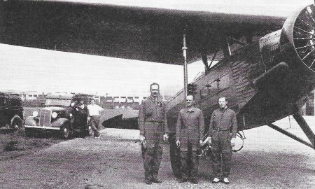
Left to right: Capts. O. J. Cram and G. V. Hallowman, and R. K. Stout, civilian engineer, who developed the Air Corps automatic landing system, before plane used in tests. By Harry Wilkin Perry, East Orange. N. J. Transport airplane operation never could have reached its present status without the aid of radio. Radio beacons guide the planes over land and sea when earth and sky are blotted out by clouds or fog. Unerringly they lead the air clippers over seemingly endless miles of ocean where navigation is difficult even in clear weather because of drift, speed, and motion of the plane which interfere with celestial observations and precise calculations. Two-way communication between airports and planes in flight bring the pilots frequent weather reports, landing and take-off orders that prevent collisions in the air, and other information pertinent to flight operation. Pilots of a fully-equipped transport plane have eighty or more instruments and controls to watch and to operate. These impose mental strain and physical fatigue, particularly in bad weather, that are inimical to safety; hence the pilots have insistently asked for simplification of control. When thick fog or a heavy snowstorm blankets an airport, flights are cancelled because of the hazard involved in manual control under such conditions.
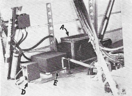
1 - Radio compass (C) connected with relay (B) and beacon receptor (D) locks directional gyro.
2 - Beacon receptor (D) and frequency selector (E) sets the frequency of radio compass; operates altitude control (A).
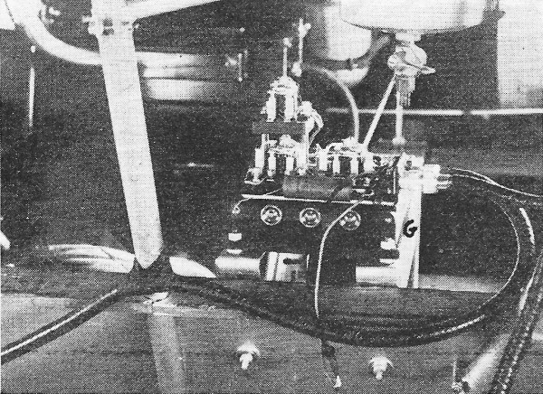
3 - The frequency selector indicator (F) shows the correctness of the automatic settings of the radio compass (C, Fig. 1).
4 - The throttle control (G) is operated by the frequency changes, controlling the throttle, and reducing speed.
5 - Landing switch (1) and auxiliary reset switches (2, 3, 4, 5) provide for hooking radio control into the mechanical pilot.
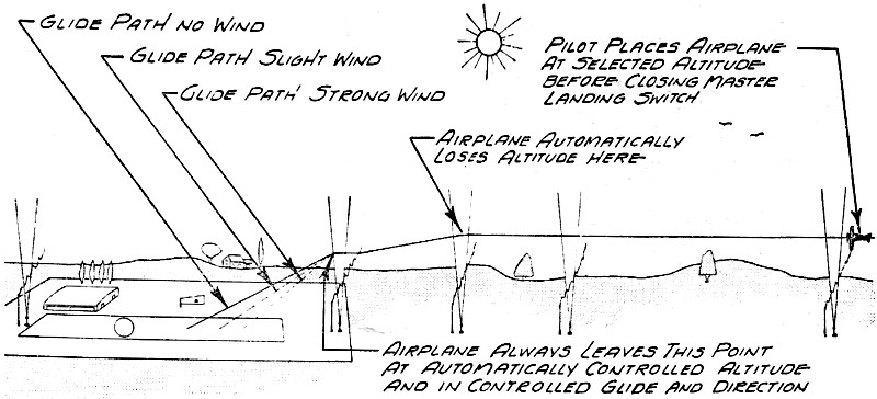
Diagram of ground antenna system showing Z-type marker beacons operating on different frequencies which transmit the signals that actuate the automatic landing apparatus. These facts led to the beginning (three years ago) of development work to simplify landing under bad conditions by making it automatic. This has now been accomplished with notable success. Many excellent landings have been made under a variety of conditions without the human pilot touching the controls. The method was made possible by a combination of radio and a robot pilot. Full details of the equipment are unavailable at present, as the apparatus is still undergoing development and has not yet reached the commercial stage and application on regular transport planes, though it probably will be in use in the near future. However, already three-quarters of the mileage (in level flight only) flown by airline transports is now done with robots in control of the planes. These mechanical pilots automatically operate rudder, ailerons, and flippers to keep the plane on course at the required altitude, and laterally balanced. They maintain more accurate and smoother flight than human pilots do, particularly in bumpy, gusty air, and relieve the latter of much tiring mental and physical effort. Twenty-two airlines, comprising most of the principal ones in the world, are using these automatic pilots on approximately 1000 airplanes in service in this country and abroad. Automatic landing, however, requires much more than maintenance of direction and level flight, and it relies almost wholly upon radio. Two different experimental methods are employed, one by the Army Air Corps at Wright Field, Dayton, Ohio, and the other by United Air Lines Transport Corporation. Both utilize radio transmitting equipment at the airport and receiving equipment in the airplane in combination with the mechanical pilot. The method employed by the Air Corps is entirely automatic, with direct connection between the radio equipment and the automatic pilot, while that used by the airline involves manual adjustment of the robot control knobs to follow radio indications down to a landing. The Air Corps system employs a series of Z-type radio range beacons located at intervals in line with the axis of the runway and extending for a distance of about five miles from the port, as in Fig. 6. Each range beacon emits waves on a frequency different from the others. In the airplane is a radio compass (C in Fig. 1), which receives the directional signals from the airport and is connected with a relay (B in Fig. 1) that interlocks it with the directional gyro to keep the plane headed directly for the port. A range beacon receptor D adjacent to relay B, and a frequency selector (E in Fig. 2) working in conjunction, automatically set the frequency of compass (C) as the plane passes successively over each range beacon and operates an altitude-control device (A). Correctness of the automatic settings is indicated on a frequency-selector indicator (F in Fig. 3). When the airplane arrives within twenty miles, or less, of the airport, the human pilot places it at a selected altitude and closes a master landing switch. The altitude is then maintained automatically by the mechanical pilot, and if the plane is not headed directly for the port, the heading is altered automatically so that it flies in the direction of the radio landing beacon. Upon reaching that beacon, the frequency of the compass is automatically changed by the receptor and the selector to the frequency of the next inner beacon, and so on to the final marker landing beacon whereupon the plane comes in to a gentle landing. These successive frequency changes actuate a throttle control (G in Fig. 4) which responds to partly close the throttle of the airplane engine, thus reducing speed for the landing glide. This throttle control is interconnected with the altitude control so that the minimum height necessary for automatic landing is maintained throughout the glide. Each successive beacon actuates the throttle to control the angle of glide and the rate of descent until ground contact is made. Finally, switches on the landing gear are connected with the throttle control. When the wheels are set down on the runway, they operate the switches automatically and cause the throttle of the airplane engine to close so the engine will idle and also simultaneously set the wheel brakes to bring the plane to a stop. It was, of course, necessary to make some addition to the mechanical pilot to provide for these automatic controls by radio. In the cockpit installation (Fig. 5) the mechanical pilot is shown at J, the master landing switch at 1, and the auxiliary reset switches at 2 to 5. It is not necessary with this system that the airplane be headed directly for the runway when approaching the airport, since the equipment will bring it into line automatically even if it should be headed directly away from the port. Many landings have been made without trouble in cross winds up to 11 miles per hour and in moderately rough air conditions. Several hundred smooth, precise landings have been made with the bent-beam system used by United Air Lines, which employs two radio beams emitted from the airport. A special transmitter sends out 93,000 kc. waves along the runway in a directional beam theoretically 5-feet wide at the landing point and 100-feet wide at the field boundary. Another transmitter operating on the same wave length emits a bent beam directed along the runway and gradually rising from the landing point to a height of 60 feet at the edge of the field, thus following the normal glide angle of the plane. [See Lauding Blind, Radio News, July, 1935.-Ed.] The airplane carries a special antenna to receive the directional and the landing impulses, which are led to a special instrument on the panel to operate a horizontal and a vertical needle. The vertical needle indicates position of the plane with respect to direction of the runway, while the horizontal needle shows its angle of glide in the landing beam. Both beams are intercepted five miles or more from the airport at an altitude of 2000 feet, and when the two needles indicate that the plane is headed directly for the runway and is at the correct height in the landing beam, the pilot throttles down the engine for a speed of about 80 m.p.h. and turns control over to the mechanical pilot. The plane then follows the landing beam on a glide that starts on a considerable angle and gradually flattens out to bring the plane to an easy, level landing near the approach end of the runway. When the tail wheel settles to the surface, the brakes are applied manually by the pilot. During the glide, the pilot watches the two needles and if either shows a deviation from course or angle, he adjusts regulating knobs on the mechanical pilot to correct the direction and angle of flight. Except for these adjustments, the landing is done entirely by radio and the robot pilot, the latter operating the controls of the airplane. An almost irresistible impulse inclines the human pilot to take a hand in the operation when making automatic landings, but experience has shown that more accurate and easier landings are made by the combination of radio and robot without any human interference.
Posted January 21, 2021 |
||