|
The advent of FET-input multimeters
greatly reduced reading accuracy errors due to not taking into account the impedance
of devices being measured. A certain amount of familiarity with how to interpret
the indication on a meter movement on analog meters is still required based on the
multiplier switch position and scale selected, but for most users simply reading
the number beneath the pointer - or interpolating its position between two numbers
- is good enough. Mirrored scales take the some of guesswork out of that by reducing
parallax issues. Finally, digital multimeters (DMMs) hit the scene and made slackers
out of just about all of us when it comes to making voltage, current, and resistance
measurements. With few exceptions, only production test, research, and metrology
environments require pulling out the meter specifications to determine precision
and accuracy numbers. Other than not exceeding the meter input limits, making a
good connection between the leads and the device under test (DUT) is important for
success. Purists and old codgers might argue otherwise, but even they probably "cheat"
when nobody is looking ;-)
Resistance Measurements
By Shepherd Litt, W2LCC
Superior Instruments Co.
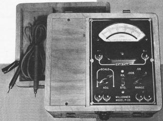
Commercially constructed ohmmeter. This instrument is highly
portable and houses a precision standard resistance which is used as a companion
when measuring an unknown resistance.
A review of the various methods used in the measurement of resistance, from
the simplest form to the more highly accurate laboratory methods. Examples are presented
whenever their use is justified and formulas worked out so that anyone, with a small
working knowledge of mathematics, can make accurate measurements.
Accurate resistance measurements are an essential part of laboratory procedure.
For some types of work, an accuracy of ±2% is adequate, while under other circumstances,
much higher accuracy is necessary. This article discusses several methods of resistance
measurement including the simple ohmmeter, the Wheatstone bridge, and the Kelvin
bridge.
Among the simplest methods that can be employed in the measurement of resistance
is the so-called ammeter method. This method, illustrated in Fig. 1A, employs
a source of potential, an ammeter or milliammeter, and the unknown resistance.
Ohm's law states that R = E/I. Resistance is equal to the voltage impressed across
a circuit divided by the current flowing through the circuit. If we employ a 1.5-volt
cell as a source of potential and impress this voltage across an ammeter and unknown
resistance in series, and the ammeter reads 0.2 ampere, the circuit resistance is
7.5 ohms. Note that 7.5 ohms is not the resistance of the unknown resistance, but
is the resistance of the entire circuit (unknown resistance, ammeter, connecting
wires and internal resistance of the cell).
To determine the resistance of the resistor, it is necessary to deduct the ohmage
of the ammeter, wires, and internal resistance of the cell from 7.5 ohm total. In
order to obtain high accuracy in this method, several points must be borne in mind.
1. Use a large cell having low internal resistance (a storage battery is ideal).
2. Use large-diameter connecting wires having low resistance.
3. Use an ammeter having a very low resistance.
4. Know the resistance of the ammeter.
5. Be sure that the ammeter is accurate.
For values of resistance above 10 times the resistance of the ammeter, the ammeter
resistance, the connecting wires, and the internal resistance of the cell may be
disregarded. The accuracy of the ammeter method can be further increased by employing
a standard resistor and basing the calculations on this standard (Fig. 1B).
Assuming that the standard resistance is 10 ohms, then, with the switch in position
No.1 the ammeter reads 1 ampere. With the switch in position No.2 the ammeter reads
0.25 ampere. Since the amount of current passing through a resistance is inversely
proportional to its resistance, then
x : 10 = 4:1; or the resistance of the unknown is 4 times the resistance of the
standard, or 40 ohms.
Note that now only the resistance of the standard need be known.
Voltmeter Method
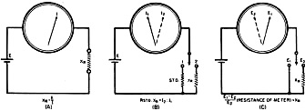
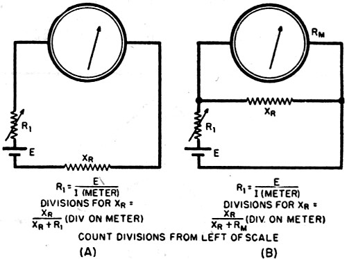
Fig. 1 - (A) Diagram illustrates ammeter method of measuring
resistance. (B) Similar to that of (A) with the exception that a standard resistance
is used as a comparison. (C) Diagram illustrates voltmeter method of resistance
measurement.

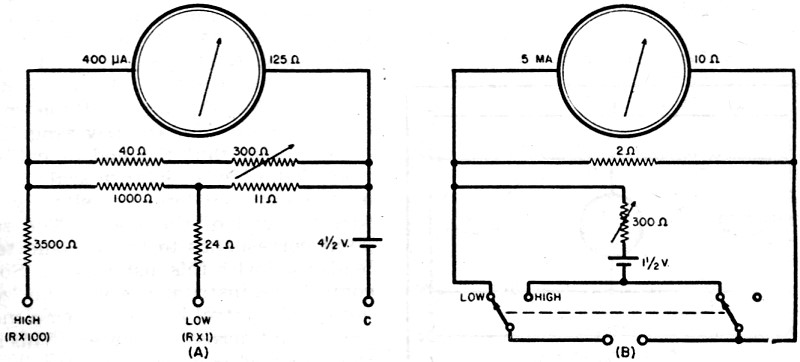
Fig. 2 - Commonly used ohmmeter. There are two versions
of this particular type: (A) Series type: and (B) Shunt type.
Should no ammeter be available, a voltmeter may be used (Fig. 1C). If E1
is the impressed voltage read by the voltmeter, and E2 the voltage read
when the unknown resistance is placed in series with the voltmeter, then
 x resistance of meter
= XR x resistance of meter
= XR
As an example, if the meter (having a resistance of 10,000 ohms) in position
1 reads 6 volts (the battery voltage) and in position 2 reads 4 volts, then
 or 5,000 ohms. or 5,000 ohms.
This is a very important formula and most commercial ohmmeters use this principle.
The voltmeter method is simple and can be used to read higher resistances than
the ammeter method. The main disadvantage of the voltmeter method is that the meter
must be capable of close reading and its resistance must be known.
The voltmeter method can also be used in conjunction with a standard resistance
to improve its accuracy. It will be described later on under Laboratory Measurements,
as it is capable of high precision.
Ohmmeter Method
The common ohmmeter is a variation of the voltmeter method. There are two types
of ohmmeters, the series type (Fig. 2A) and the shunt type (Fig. 2B).
In the series type, a battery, a milliammeter, and a resistor are connected in
series with the unknown resistor. The resistor is made variable so that the meter
can be brought to full scale. As such, the resistor and the meter constitute a voltmeter
which can be brought to full scale to correspond to the voltage of the battery.
The value of the resistance required can be computed by Ohm's law.
If a 1-ma. meter and a 4.5-volt battery are used, the series resistor would then
be 4500 ohms.
This can be made up by using a 3000-ohm resistor and a 1500-or 2000-ohm adjustable
control. With the unknown resistance terminals shorted, the meter is made to read
full scale by varying the adjustable control. The unknown resistor is then put in
the circuit and the reading noted. If the unknown resistance were to be 4500 ohms,
the total resistance in the circuit would be 9000 ohms and the 1-ma. meter would
become a 9-volt voltmeter, Since a 4.5-volt battery is being used as a source of
potential, the meter will read half scale. A resistance lower than 4500 will cause
the meter to read more than half scale, while a resistance greater than 4500 ohms
will cause the meter to read less than half scale. Zero resistance, therefore, will
correspond to full scale and would appear to the right of the meter scale. If a
meter having a regular linear scale is used, the scale can be changed to an ohmmeter
scale by employing the following formula:
 x divisions on meter x divisions on meter
when R1 = meter resistance (as a voltmeter), R2 = unknown
resistance.
Using the above-mentioned meter and battery as an example, and if the meter is
a 1-ma. type with 4500 ohms internal resistance and with 50 divisions on the scale,
and the battery is 4.5 volts, a 4500-ohm resistor would read:
 or 25 divisions on the
50-division scale. or 25 divisions on the
50-division scale.
A 10,000-ohm resistor would read 16 divisions on the same scale, and a 500- ohm
resistor would, in like manner, read 45 divisions.
The above method is the method employed by the writer in calculating the resistance
scales for one manufacturer in the instrument field.
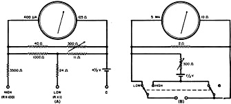
Fig. 3 - (A) Ohmmeter employing a zero adjusting control
that is placed in shunt with the meter. (B) Commercial-type ohmmeter based on both
the series and shunt circuits.
In order to reduce the range of the meter, a shunt can be employed. By using
a shunt to change the aforementioned 1-ma. meter to 10 ma. and reducing the series
resistance to 450 ohms, a reduction ratio of 10 is brought and the center of the
resistance scale then becomes 450 ohms. To increase the range of the ohmmeter, either
a 45-volt battery and 45,000-ohm resistor can be employed with the 1-ma. meter,
or the meter sensitivity can be increased 10 times to 100 microamperes.
In the above ohmmeter, the resistor in series with the meter acts as a "zero
adjuster control" to compensate for battery voltage changes. In multi-range instruments,
this "zero adjuster control" must be made with a special taper so that it can be
employed successfully to vary the meter on all ranges. It is often better to place
the control across the meter and use a fixed series resistance. This is advantageous
because the control has a much better adjustment in this position and the circuit
can be proportional, so that no adjustment need be made when changing ranges. Fig. 3A
shows such a circuit.
The low range of the instrument is 0-5000 ohms, with 35 ohms center scale; and
the high range is 0-500,000 ohms, with 3500 ohms center scale.
The series type of ohmmeter is the most common type of ohmmeter in use today,
its accuracy being normally 2% of the linear arc; i.e., if the arc of the meter
is 90°, then all readings are accurate to 1:8° at any part of the scale.
Although the series ohmmeter is often used for low resistance measurements, it
has been deemed advisable to use another circuit in place of it. Referring back
to the circuit of Fig. 3A, the low range consists of the 24- and 11-ohm resistors
in series with the unknown and the 4.5-volt battery. If the unknown resistance is
10 ohms, a total of 45 ohms is in series with the battery. Neglecting the current
used to actuate the meter, this means that a current of 100 ma. is being taken from
the battery, and if used continually for low resistance testing, would exhaust the
battery. To circumvent this, the shunt ohmmeter is used.
The shunt type (Figure 2B) is the series ohmmeter with the leads shorted and
the resistance placed across the meter. The effect of the resistance in this position
is to act as a shunt across the meter to reduce the scale reading. Since a short
across the meter will cause the meter not to read at all, the zero point corresponds
to the zero of a regular voltmeter, pointing to the left and the "infinity" mark
to the right.
The formula for calculating the shunt ohmmeter is exactly opposite that for the
series ohmmeter, and can be written:
x divisions of the meter
scale.

Fig. 4 - Scale divisions of a commercially built ohmmeter.
Superior Instruments Company's model 1552.
Because of this fact, the resistance of the meter appears in the center of the
scale.
The shunt ohmmeter finds its chief use in measuring resistances less than 100
ohms. If the meter is to measure resistances less than 6 ohms, the length and resistance
of the test-leads must be figured into the computation of the scale. A pair of commercial
test-leads (36") has a resistance greater than 0.06 ohms. If the resistance were
not taken into account when the scale of the meter was computed, an error of 1%
would exist at the 6-ohm point. The error at 0.6 ohms would be 10%. If the resistance
of the test-leads were added to the meter resistance, the error would be eliminated.
A typical commercial ohmmeter employing both series and shunt circuit is diagrammed
in Fig. 3B. This is a commercial ohmmeter manufactured by Superior Instruments
Company, their model 1552. The scale of this instrument is shown in Fig. 4.
The series ohmmeter is used for the high range of 0-1000 ohms and the shunt ohmmeter
used for the low range 0-10 ohms. Note that the end of calibra-tion of the low resistance
scale is not at the extreme left, but slightly before the end of the scale. The
zero point corresponds to the 0.06 ohm test-leads used with this instrument. Some
commercial instruments omit the "zero adjuster" control by employing a magnetic
shunt across the meter. This has the effect of increasing or decreasing the sensitivity.
The above methods are commercial methods in use today and, unless extreme precautions
are taken, cannot successfully be used to measure better than 2%. To achieve a higher
degree of accuracy, laboratory methods must be used. Two general methods are employed
in the laboratory: the potentiometer method and the bridge method.
In the potentiometric method, the voltage drop across the standard resistance
is compared to the voltage drop across the unknown. It can best be described as
the voltmeter method used with a standard resistance. (A potentiometer is an instrument
measuring voltage below 1.6 volts, employing a null method. It is adjusted and calibrated
by means of a standard cell and has an accuracy of better that 0.05%. Most laboratory
potentiometers have an accuracy of 0.01% and 0.02%)
In the method employed, current is sent through both the standard resistance,
usually having an accuracy of 0.05 % or better, and the unknown resistance. The
voltage drop across the standard is read first, and then the drop across the unknown,
by means of the potentiometer. If, for example, a standard resistance of 1 ohm is
used and the voltage drop across it is found to be 1 volt, with the voltage drop
across the unknown 1.016 volts, the unknown resistance is 1.016 ohms. This is true
since the same current that passed through the two resistances makes their voltage
drops proportionate to their resistances.
A commercial instrument utilizing this principle, the model P-25, manufactured
by Superior Instruments Company, operates on the following principle: A current
is sent through a precision standard resistance and the unknown. The voltage drop
across the standard is adjusted until the meter reads full scale, by means of a
control and a momentary "standardizing" switch. When the switch is released the
drop across the unknown is read. Although the instrument really measures voltage
drops, the scale is calibrated in ohms. The indicating instrument is a precision
mirror-scale millivoltmeter, having 100 divisions. Range of the instrument 0 - 0.005,
0 - 0.05, 0 - 0.5, since it was made primarily to measure low resistances such as
solid rods of metals, switch contacts, etc. The lowest reading possible is 0.00005
ohms with the limit of error 1 division or 1% at any part of the scale. Readings
can be estimated to 1/4 division. Although this instrument was made primarily to
measure low resistances, it can be converted to read high resistances by a small
change in wiring. It should be especially noted that the scale of this and similar
instruments operating on the same principle are linear, as compared with the crowded
scales of ordinary resistance meters.
The more common type of laboratory resistance meter is the bridge. There are
two basic types of bridges: the wheatstone bridge, for measuring resistances above
0.1 ohm, and the Kelvin bridge, sometimes called a double bridge, for measuring
resistances below 1 ohm.
Wheatstone Bridge
A Wheatstone bridge (Fig. 5) is a closed resistance network of four arms.
Two of the arms (A and B) are ratio arms and are usually fixed resistances. The
C arm is a variable arm, usually fixed resistances controlled by a switch and made
so up to 1000 ohms in 0.1 ohm increments. The X arm is the unknown resistance. A
source of voltage is, in most cases, applied between the B and C arms and the A
and X arms. A galvanometer, having high voltage sensitivity, is connected between
the junctions of the A and B arms and the C and X arms. Balance of the bridge (no
galvanometer reading) is had when:

The accuracy of commercial laboratory Wheatstone bridges runs from 0.5 of 1%
in portable models to 0.02 % in high precision models.
A variation of the Wheatstone bridge employs a slide wire in place of fixed ratio
arms and a fixed resistance standard in place of the C arm. Although the accuracy
of the slide-wire bridge is usually less than that of the fixed-ratio bridge, it
has the advantage of greater speed in reading.
Kelvin Bridge
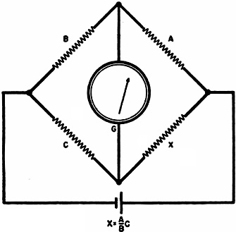
Fig. 5 - Wheatstone bridge.
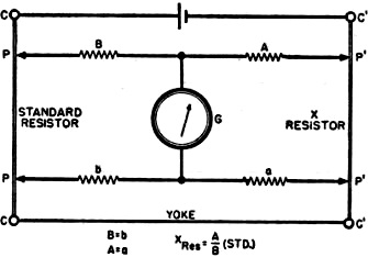
Fig. 6 - Kelvin bridge.
The Wheatstone bridge cannot be successfully used to measure low resistances.
If we take a bar of metal and try to measure its resistance by means of a Wheatstone
bridge, several important facts must be borne in mind. The resistance of the connecting
leads must be accurately known, since they contribute to the resistance indicated
by the bridge. Resistance of the contacts between the bar and the connecting wires
must be known for the same reason. By employing large low-resistance cable as connectors,
the former can be deducted from the bridge reading, but the latter (contact resistance)
can never be accurately known. Because of this fact, the Wheatstone bridge is never
used to measure below 0.1 ohm, although theoretically it is possible.
In the Kelvin bridge, the resistance of the connecting leads and contacts are
unimportant since they are put in series with the comparatively high-resistance
ratio arms. This can be done only by employing current and potential terminals for
both the standard and the unknown resistance. The resistance measured by the Kelvin
bridge is the resistance between the potential leads only. Fig. 6 illustrates
the operation of the Kelvin bridge.
A and B: The regular ratio arms similar to those employed in a Wheatstone bridge.
a and b: A duplicate set of ratio arms.
Yoke: This is the connecting bar between the standard and the unknown. Note that
a and b shunt the yoke and therefore its resistance does not enter into the calculation.
C and C: The current connections of the standard resistance.
C' and C': The current connections of the unknown.
P and P: The potential leads of the standard.
P' and P': The potential leads of the unknown.
G: The galvanometer that is used to indicate when the bridge is balanced.
Since all the heavy current goes through the current terminals (there is only
a low circulating current flowing through the ratio arms) the contact resistance
of the potential leads has no effect on the measured resistance. A commercial laboratory
version of a high precision Kelvin bridge is that manufactured by the Leeds &
Northrup Company and comprises two units, the 4320 dual ratio box and the 4300 low
resistance standard.
The dual ratio is made up of 10 resistors, two each of 100-300-400-1000 and 10,000
ohms. These coils are adjusted to better than 0.05 % of their nominal value. They
are controlled by plugs and give ratios of 100, 10, 1, 0.1, and 0.01 of the standard.
Other ratios can be had by inserting the plugs into other combinations of jacks.
Since the lowest ratio arm resistance is 100 ohms, contact and lead resistance can
be as high as 0.01 before an error of 0.01% is had from this source. In practice,
contact and lead resistance is much less than 0.01 ohm.
In this case, the standard resistance consists of nine coils, each 0.001 ohm,
plus a calibrated bar 0.0011. These resistances are accurate to 0.02%. The nine
coils in conjunction with the calibrated bar have the effect of a bar 10 times as
long. Nine coils can carry a current of 50 amperes continuously and the bar alone
can carry 150 amperes. The bar is calibrated to 100 divisions, and a vernier screw
allows readings down to 0.1 division. Range of this Kelvin bridge is from 0.000,000,011
to 1 ohm, with an accuracy of 0.04%.
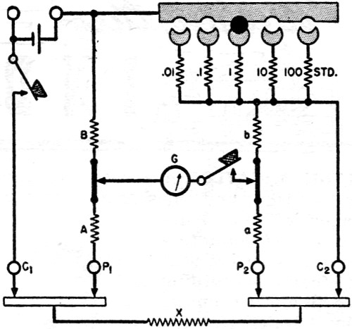
A portable Kelvin bridge is diagrammed in Fig. 7. This is the Leeds &
Northrup type 4286 Kelvin bridge ohmmeter. The portable bridge compares the unknown
resistance against 5 standard resistances by means of a dual ratio arm that is variable.
Resistance of the unknown is equal to the dial setting of the ratio arms multiplied
by the standard in use, with the dial calibrated 0.01 to 0.11 ohms. The range of
the portable bridge is from 0.0001 ohm to 11 ohms, and the error is less than 2%
of the setting.
Special Circuits

Fig.7 - Diagram of Leeds & Northrup portable type 4286 Kelvin
bridge ohmmeter.
Besides the above mentioned methods, special circuits are sometimes used:
The No.1 Weston ohmmeter uses a D'Arsonval movement, but with a tapped coil.
The current through one coil remains constant, while the current through the second
section varies with the resistance connected across the meter terminals. Its coils
are so wound that when no resistance is in the circuit, the torque of the two coils
are equal and the meter reads zero. When a resistance is inserted in the circuit,
the current in the "resistance" coil only partially nullifies the current of the
"current" coil, causing the meter to read up scale. Provisions are made for adjusting
the meter by means of a magnetic shunt to compensate for aging of the battery. A
mirror scale is provided and the scale is very close to linear.
The megger is an instrument, formerly made in England but since the war manufactured
in the United States, that is used primarily to measure insulation resistance. The
instrument consists of a dual (current and voltage) coil, shaped like a T, rotating
in the field of a permanent magnet. No springs are used in the instrument. The magnet
also supplies the field for a small d.c. generator with a potential of 500 volts,
which is operated by rotating a hand crank. In operation the crank is rotated and
the 500 volts generated is applied to the voltage coil, turning the coil so that
the pointer appears at the "infinity" mark on the scale. 500 volts is also applied
to the resistance (insulation) through the current coil. The torque produced by
the current passing through the current coil and the insulation resistance, opposes
the torque of the voltage coil, causing the pointer to swing away from the infinity
mark to a point on the scale corresponding to the resistance being measured. A "megger"
finds its chief use in measuring insulation resistance where a source of power cannot
be had. The range of this instrument is usually 100 megohms and 500 volts. Special
instruments can be had to measure resistance up to 20,000 megohms at a test potential
of 2500 volts.
A special resistance meter recently designed by the writer is worth describing.
It operates on the bridge principle, but in place of a null indicating meter, the
meter is calibrated from 1 to 10. The range of the instrument is from 0.1 ohm to
10 megohms in decade steps - i.e., 0.1 ohm to 1 ohm, 1 to 10 ohms, 10 ohms to 100
ohms, etc. With a meter scale of 90 divisions, each division represents 1% of full
scale. The meter can be read with ease to 1/4 division or 25% of full scale. The
meter has been built in several ways. It has been used as a limit bridge, a temperature
bridge, and a resistance meter. As a limit bridge it has been made as sensitive
as ± 0.1% of the standard in use. As a resistance meter it has replaced a regular
bridge, since it is speedier in operation; resistances are measured as quickly as
in a conventional ohmmeter, but with the accuracy of a bridge.
Methods other than outlined above have been occasionally used in resistance measurements.
However, they are not as common and are seldom used.
Posted January 26, 2022
(updated from original post on 5/1/2015)
|