|
 Prior to the advent of thyristors
and semiconductor lamp and motor control circuits, a relatively simple and safe
- although heavy and bulky - method for controlling AC voltage was with the use
of saturable core transformer arrangements. By using a DC winding to control the saturation level of the transformer
core material, the inductance, and therefore inductive reactance, of secondary windings
can be controlled. Doing so has the same effect as using a
Variac that uses mechanical control
of the coupling and transformer voltage input/out ratio. The method shown here has
a potentiometer for adjusting the DC current level, but, as the author mentions,
electronic control circuits were/are also widely used. Prior to the advent of thyristors
and semiconductor lamp and motor control circuits, a relatively simple and safe
- although heavy and bulky - method for controlling AC voltage was with the use
of saturable core transformer arrangements. By using a DC winding to control the saturation level of the transformer
core material, the inductance, and therefore inductive reactance, of secondary windings
can be controlled. Doing so has the same effect as using a
Variac that uses mechanical control
of the coupling and transformer voltage input/out ratio. The method shown here has
a potentiometer for adjusting the DC current level, but, as the author mentions,
electronic control circuits were/are also widely used.
Saturable Reactors
By Erwin Levey
 Details on a saturable reactor that can be quickly
assembled using two standard power transformers. Details on a saturable reactor that can be quickly
assembled using two standard power transformers.
The operating principles of saturable reactors have been known for quite a long
time, but it is only within the past few years that these units have come into general
use. Considering the reactor's versatility, the number of ways in which it can be
used is almost unlimited. Basically it is a magnetic device which functions as a
variable inductance. It has a d.c. winding which is used for control and an a.c.
winding which is connected in series with the load to be controlled. There is no
direct connection between the two circuits, the only linkage is through the magnetic
properties of the core on which they are both wound.
Operation is based on the phenomenon that the permeability of a magnetic material
is not constant. It varies with the strength of the magnetizing force applied. Since
the inductance of a coil is directly proportional to the permeability of its core
material, it also will vary. When the d.c. control current is zero the permeability
of the core is extremely high, therefore the inductance of the a.c. coils is large.
Since they are connected in series with the load the load current is extremely low.
As the d.c. control current is increased the magnetizing force through the core
is increased. This causes the permeability and therefore the inductance of the a.c.
coils to decrease. This, in turn, means that the load current will also increase.
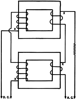
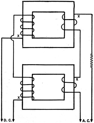
Fig. 1. - Terminal connections of saturable reactor using
two separate transformer cores.
As the d.c. current increases further the inductance is proportionately decreased
with a corresponding increase in load current. When the core is fully saturated
with full d.c. current the inductance of the a.c. coils is minimum. Therefore it
can be seen that the control effect is secured by means of d.c. core saturation.
Since the d.c. power required for control is less than the a.c. power used in the
load circuit the unit has a certain amount of gain or amplification.
Physically a saturable reactor has the same general type of construction as a
transformer although several different types of core arrangements are possible.
The one described here is extremely simple and is assembled by using only two standard
transformers.
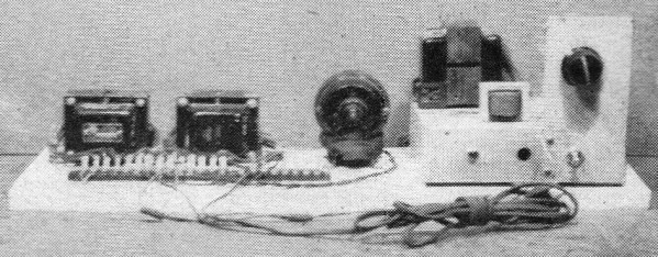
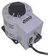
Fig. 5 is a photograph of a unit which was assembled breadboard style for
ease of construction. The two small transformers on the left are used as the saturable
reactor, the small motor being the controlled unit. The chassis on the right is
the variable d.c. power supply used for control purposes. Fig. 4 gives a close-up
of the reactor unit alone, from which it can be seen that the transformer windings
are connected to a screw-type terminal strip. This procedure facilitates connections
and requires only a screwdriver for assembly.
Before proceeding further, several terms which identify multiple coil connections
will be explained in order to clarify the main explanation to follow. In a "series-aiding"
connection two coils are connected together so that their relative winding directions
are the same. The net result is that the voltage induced in each is in the same
direction, while the total terminal voltage equals the sum of the two individual
voltages. In a "series-opposing" connection the two coils are connected so that
the relative winding directions are opposite, producing voltages in opposite directions.
Here the total terminal voltage is equal to the difference of the two individual
voltages. It is important to note that these relative winding directions are given
from an electrical viewpoint, and not in terms of the actual physical windings as
they are placed on the core.
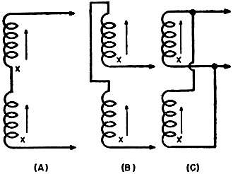
Terminals of similar polarity or winding direction are indicated by means of
an X. This end is called the "start," the other end is the "finish." The conventions
that will be used throughout this article are illustrated in Fig. 3, which
also shows the proper type of parallel connection. To avoid confusion they are defined
specifically at this point.
As pointed out earlier in the article several different types of core arrangements
are possible. The one which will be explained here as the basis for the unit to
be constructed is the simplest type from an experimental viewpoint. A schematic
of the unit is shown in Fig. 1.
Two separate, identical cores are used, each having a d.c. and an a.c. winding.
Both a.c. windings are identical, so are both d.c. windings. However, the d.c. windings
differ in physical characteristics from the a.c. windings. Since each d.c. coil
is on a core with an a.c. winding there will be an a.c. voltage induced in the d.c.
windings due to transformer action. Now, if the two d.c. coils are connected in
series-opposing, the a.c. voltage induced in each will cancel, as a result of their
being equal in magnitude but opposite in polarity. This is the only permissible
connection for the d.c. coils. But the series-aiding connection for the a.c. coils,
as shown in the diagram, is only one of the possible connections for them. The unit
to be described here is based on this type of arrangement, as explained before.
For this purpose, two identical 40 ma. power transformers were used, each having
the following windings: primary (117 v.), high voltage (480 v.), 5 v. filament,
and 6.3 v. filament. All the secondaries had center taps but they were taped up
since they were not used. Actually, for the construction of a simple unit only the
primary and high voltage windings are needed but the low voltage windings can be
used to show some further interesting control possibilities. The primary is used
as the a.c. coil and the high voltage winding as the d.c. coil.
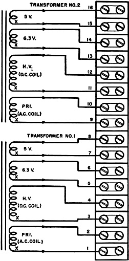
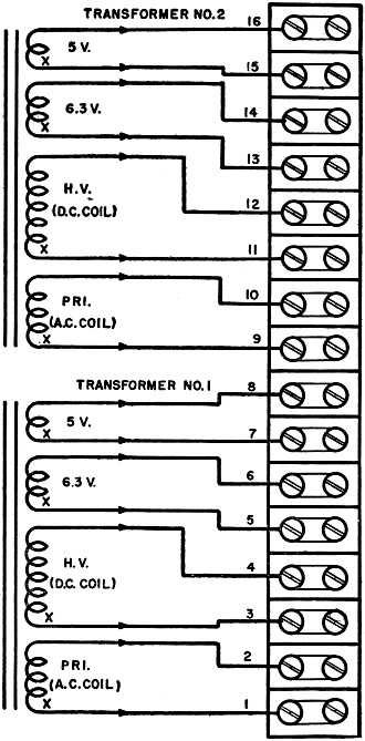
Fig. 2. - Transformer winding connections.
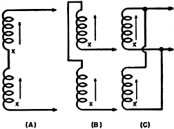
Fig. 3. - Coil connections. (A) series-aiding. (B) series-opposing.
and (C) parallel.
Once the transformers and terminal strips have been mounted the windings are
connected in the following order: primary, high voltage, 6.3 v. filament, and 5
v. filament. The order is the same for each transformer. At this point actual physical
order of the two leads of a particular winding do not matter.
The next and most important step is to properly phase .all the windings, that
is, to determine their winding directions with respect to the primary as the standard.
The procedure will be explained first for transformer #1 separately. Since the primary
is used as the starting point the connection to the first terminal is called the
start, the second connection, the finish.
Connect the finish of the primary to the high voltage lead immediately adjacent
to it. Then connect the primary leads to 117 volts and read the voltage appearing
across the two coils which are now in series. If the reading is the sum of the two
individual voltages the coils are connected in series-aiding, this being the condition
desired and indicating that the high voltage leads are in the proper physical order.
On the other hand, if the difference of the two voltages is indicated, the connection
is series-opposing. If this is the case, reverse the positions of the high voltage
leads and repeat the test. The reading will then indicate a series-aiding connection.
For each set of winding leads, the first one in physical order should be the start;
the second, the finish. If low voltage windings are present repeat the procedure
exactly as described using the primary and each winding individually. The complete
procedure should be repeated step-by-step for the windings of transformer #2.
The purpose of this test can be seen by referring to the schematic diagram in.
Fig. 2. The windings are laid out in standard order to facilitate the actual
interconnection of the units as a saturable reactor. This is the most crucial step
in the whole procedure and a double check should be made to make sure that no errors
exist. Otherwise the unit will either operate improperly or not at all.
As explained previously, the d.c. coils (high voltage windings) must be connected
in series-opposing. Following the original definition this is done by connecting
the finish of high voltage #1 to the finish of high voltage #2. The d.c. voltage
source is then connected to the two remaining leads, which are the start of high
voltage #1 and high voltage #2. In this simple arrangement the unit is not polarity
sensitive, that is, the positive lead could be connected to either end. However,
to keep a standard procedure (necessary for later arrangements), start high voltage
#1 will be designated the plus terminal and start high voltage #2 the negative terminal.
Next, the two a.c. coils (primaries) are to be connected in series-aiding. Therefore
connect finish of primary #1 to start of primary #2. These coils are then connected
in series with the load to be controlled. The actual schematic of this set-up is
shown in Fig. 6A.
At this point it is necessary to determine the range of the unit. The size of
the wire in the primary windings (a.c. coils) is determined by the power (actually
current) used under actual load conditions for which the transformer was originally
designed. This is done in the following manner: Total secondary power equals power
of each individual winding.
The assumption will be made that this is the same as ·the input power. This is
not exactly true in the case of an actual transformer but it is found that the assumption
is close enough to give an idea of the range, which is all that is necessary. Thus
it is shown that 40 watts is the limit due to the physical properties of the unit.
The actual amount of power that can be controlled is somewhat less, approximately
30 watts. From experimental results it was found that the d.c. current necessary
for complete control when the high voltage windings are used as the d.c. coils was
equal to the current rating of the high voltage windings plus 10% of that amount,
in this particular case, 44 ma. The unit used for control was a regular variable
power supply rated at 300 volts with no load. It is best to use a light bulb of
the proper wattage as the load so that the control effects can be observed visually.
When all the connections have been made, with the d.c. power off, plug in. the
a.c. load circuit. At this point the bulb will be either completely extinguished
or else very dim. Now turn on the d.c. power supply and slowly increase the current.
The brightness of the bulb will increase in proportion to the current, reaching
its maximum brightness at approximately 44 ma.
When the core is fully saturated at full d.c. current and the bulb is at its
maximum brightness it will be found that the voltage appearing across the bulb is
less than the actual line voltage (approximately 100 v.). This is due to the fact
that the reactance of the coils cannot be decreased to exactly zero. As a result
there will always be some drop across the reactor. In commercial applications this
is corrected by providing a supply voltage which is about 5% higher than the normal
operating voltage of the controlled unit.
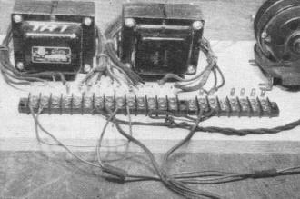
Fig. 4. - Close-up of reactor. Two small transformers are
used.
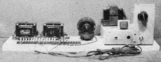
Fig. 5. - Breadboard assembly of saturable reactor motor
control.
At the other extreme it will be found that the lamp voltage does not drop to
zero, since the reactor cannot be infinite in value. This of course means that the
load current cannot be decreased to exactly zero. However in the case of a lamp
load it will "black-out" at approximately 15% of full line voltage. When a resistive
load is used the two voltages, across the reactor and across the resistive load,
are 90 degrees out-of-phase. When the load is also reactive, for example a motor,
the voltages will be in-phase. The net result of all this is a slight reduction
in the control range.
In the next arrangement the two a.c. coils will be connected in parallel. Again
following standard convention the finish of primaries #1 and #2 are connected together
and the start of these same windings are connected together. The start ends are
connected to the a.c. line and the finish ends are connected to the light bulb and
then to the other side of the line (coils in series with load unit). The d.c. coil
connections are not changed. The actual schematic of this circuit is shown in Fig. 6B.
When using this connection it will be found that the d.c. control current needed
is only one-half of that required for a series connection of the a.c. coils. It
will also be found that the unit will operate much more efficiently in this arrangement.
This results from the fact that the primaries were originally designed to operate
on 117 volts.
If desired, a small fractional horsepower motor can be substituted for the light
bulb. Its power rating must be approximately the same as the light bulb used. For
this purpose, the type of motor used in
Erector Sets or small movie projectors is the proper size, but
it must be a 117 volt a.c. type.
It is necessary to observe certain precautions, because when a motor first starts
it draws an excessive line current which is higher than its normal value at full
speed, with the consequent danger of overloading the unit. To avoid this a shorting
switch is connected across the a.c. coils so that full line voltage can be applied
to the motor. Once the motor is started the switch is opened, changing the control
of the motor to the saturable reactor.
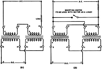
Fig.6. - Saturable reactor with a.c. coils connected in series
(A) and in parallel (B).
In order to simplify specific arrangements and procedure the foregoing explanation
has been based on the ratings of a 40 ma. power transformer. However, units have
been built using 70 ma., 90 ma., and 150 ma. transformers and the system is exactly
the same when any of these are used.
The gain of the unit can be calculated by the following formula:
gain = output power (a.c.) / input power (d.c.)
The gain of the small unit is relatively low, but as the size of the unit is
increased the efficiency also increases which means that the gain is higher. The
cores used are made of 4% silicon steel which operate best at high power levels.
Manual control has been used in this presentation to avoid complications. There
are several very interesting ways in which these units can be controlled by means
of regular electron tubes.
In the beginning of this article it was pointed out that a multiple control unit
can be made by making use of the low voltage windings, making possible control based
on multiple input signals. Once the unit is assembled it is merely necessary to
connect the proper type of control unit to each set of windings. Since the windings
are different from the high voltage windings the control conditions are entirely
different. Therefore it would be necessary to experiment in order to determine the
best control conditions for each of the various voltage windings.
Posted April 7, 2023
(updated from original post on 6/27/2016)
|