|
If you are looking for
information on the Crosley SCR-284 Field Radio, you've come to the right place -
at least for learning about how manually intensive the manufacturing process for
it was. If you want to know about the history and operation, then you'll want to
visit the N6CC (Navy 6
Combat Comms) website. It is a wealth of amazing details, including, "The
SCR-284 was used extensively during WWII. The basic component is the BC-654-A
receiver transmitter. Designed as a portable field radio, the complete field set
could be carried by 3 men (three 55 pound loads) or it could be mounted in
vehicles. US Army procurement records indicate that 63,972 sets were procured
between 1940 and 1945. Apparently all were built by Crosley Corp." That works
out to more than 10,000 units per year, each requiring the kind of assembly and
testing shown here. Along with the highly skilled and dedicated labor force
required to turn out such quantities (while also producing other equipment) are
the design, test, and production engineers needed to dream up, implement, and
support such a massive effort. This same sort of thing was being done all across
the country during World War II by patriotic Americans who wanted to do their
parts to back the troops fighting to beat back Nazism, Communism, Socialism, and
all the other forms of governmental "isms" which sought to dominate the world
and affix the yoke of tyranny on its people. How soon some forget and/or fail to
teach the next generation of the evils of those "isms."
The SCR-284
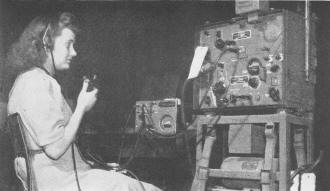
Signal Corps test of SCR-284-A, using PE-103-A dynamotor to supply
power to the transmitter.
By D. V. Noble
Chief Trans. Eng., Crosley Corp.
A description of the SCR-284 together with a picture story of techniques used
in manufacturing and testing this set.
In the all out effort to defeat the Axis it was necessary for many manufacturers
to build radio equipment to exacting Signal Corps specifications, which was a far
cry from the standard broadcast receivers they had been used to making. Factory
layouts had to be changed and personnel retrained to make and handle precision radios.
The award of a production contract for the SCR-284-A Field Radio equipment to the
Crosley Corporation meant that it had to train its people to make and test receivers
and transmitters, dynamotors, hand generators, and all antenna equipment and accessory
parts. The SCR-284-A is a complete portable and mobile radio station.
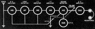
Fig. 1 - Block diagram of the conventional receiver circuit.
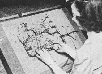
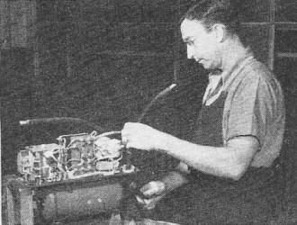
Making receiver and transmitter harness on cable board, according
to blueprint specifications.

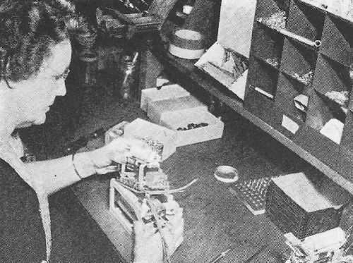
Keying relay and capacitors being placed on antenna-tuning coil,
making a complete sub-assembly.

Mounting trimmer condenser on transmitter chassis. Junction blocks
are on rack.
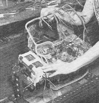
A laced cable harness is placed in the transmitter chassis.

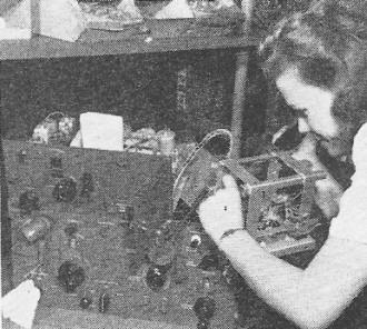
Cable harness and components being soldered to terminals on bottom
of transmitter.
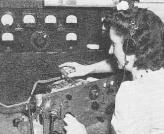
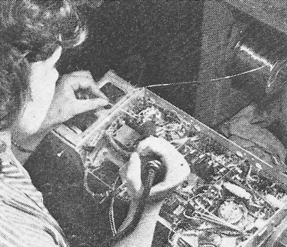
Aligning transmitter for proper performance in specially-equipped
and shielded booth.
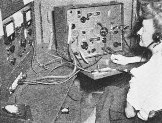
Receiver being aligned in another shielded booth.
Receiver and transmitter being joined together on the "marriage
line."
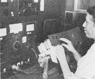
Final inspection of a BC-654-A by a U. S. Signal Corps inspector.
Final assembly of the PE-103-A dynamotor power unit which supplies
power for the transmitter for vehicular operation.
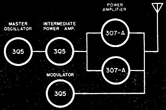
Fig. 2 - Block diagram of the transmitter.
The electrical specifications for the SCR-284 are as follows:
1. Use: As a portable or vehicular set
2.Transportation: By vehicle or carried by foot soldiers
3. Range: (Transferred into electrical characteristics.)
Receiver
Sensitivity 3 μv. for c.w. and 5 μv. for voice with a 10/1 signal-to-noise
ratio.
Transmitter
Power output 20 watts for c.w. and 5 watts for voice.
Frequency Range: To be continuously variable from 3800 kc. to 5800 kc. Receiver
dial to be calibrated directly in frequency and the transmitter to be calibrated
accurately every 10 kc.
4. Power Supply: For vehicular use, from a 6- or 12-volt vehicular storage battery
with either the positive or negative side grounded.
For field use, from a hand-operated generator for transmitter with the generator
output not to exceed 50 watts. The receiver to obtain its power from a dry battery
pack.
Quick-heating filament type tubes to be used throughout.
5. Miscellaneous: The number of controls to be as few as possible. A 200 kc.
calibration crystal to be used for calibrating the transmitter. The set must be
capable of "netting" without radiation of power. A list of applicable specifications
included for guidance of designs.
The block diagram of the receiver circuit shows that it is more or less of conventional
design. An r.f. stage is used to amplify the received signals before they reach
the first detector which is a combination detector and oscillator stage. The resultant
intermediate frequency is amplified by two stages of intermediate-frequency amplification.
The signals are then rectified by a second detector which provides a.v.c. voltage.
This controls the sensitivity of the radio-frequency and intermediate-frequency
amplifiers.
The audio signals are amplified by an audio-frequency stage which in turn delivers
power to a pair of headsets or loudspeaker. For c.w. operation a beat frequency
oscillator, oscillating at the i.f. frequency, mixes with the incoming signals at
the second detector, thus providing a beat note for keyed signals.
The a.v.c. circuit is disconnected by means of a switch for c.w. reception so
that the r.f. and i.f. amplifiers operate at maximum sensitivity, the final volume
level being determined by a volume control which varies the amount of signal sent
into the a.f. amplifier.
When this set is to be used in the field, the specifications require that all
of the receiver power be obtained from a dry battery. Hence, it is mandatory that
1.4-volt filament type tubes be used throughout with as low a screen and plate voltage
as is necessary to produce the over-all characteristics.
The SCR-284 receiver uses a 90-volt supply for the plate power with appropriate
dropping resistors for the screen voltage. The over-all sensitivity requirements
for a 10/1 signal-to-noise ratio was 3 microvolts for c.w. and 5 microvolts for
voice operation, but present actual production is now running with a c.w. sensitivity
of less than 1 microvolt and a corresponding decrease for voice operation. An output
of approximately 150 milliwatts is available from the a.f. amplifier which makes
it possible to operate a small loud speaker. This gives sufficient volume to be
heard at a considerable distance from the radio set and makes it unnecessary for
the operator to wear headphones and be constantly at the radio set during long standby
periods.
The receiver has only two controls, a tuning knob and a volume control. All switching
is done by switches on the transmitter.
Transmitter
The block diagram of the transmitter indicates a conventional transmitter as
far as the tube lineup is concerned. In the interest of standardization an effort
was made to limit the number of types of tubes to a minimum in both the transmitter
and receiver and since a 3Q5 tube was used in the receiver audio-frequency power-output
amplifier, this tube was used in the transmitter in all socket positions except
for the power amplifier. This circuit consisted of a master oscillator, an intermediate-frequency
power amplifier, a power amplifier and a modulator for voice operation.
The power amplifier used two Western Electric 307-A tubes in parallel which required
a 500-volt plate supply and approximately 250-volt screen supply. At first thought
it seems that this power amplifier is overly large for this set since each of the
307-A tubes is capable of delivering approximately 20 watts of c.w. power output,
but since the specifications require an output of 20 watts into a vehicular antenna
(which is actually the equivalent of 8 ohms in series with 110 μμfds, of capacity)
it becomes evident that the antenna-tuning network for this type of antenna must
consume considerable power.
A further requirement for this set was that it work into practically any kind
of antenna including a conventional single-wire voltage-fed half-wave antenna, vertical,
L or T antennas and finally into merely a piece of wire lying on the ground. This
required a special antenna network. The resulting power loss in such a network is
approximately equal to the power output delivered to the antenna which thus made
it necessary to develop 40 watts of tube power. This meant putting two of the WE-307-A
tubes in the final amplifier stage, but caused no particular hardship since one
3Q5 intermediate amplifier was quite adequate to drive two 307-A tubes.
In the interests of simplicity, and to make the operation as simple as possible,
all frequency-determining elements of the transmitter are controlled by one four-section
gang condenser which makes this transmitter a single-control tuning set. Three other
controls are necessary for proper loading of the transmitter into various antennas,
one of which consists of the antenna selector switch (which determines the type
of network that will be used), a series antenna-tuning coil, and a voltage-coupling
coil (which determines the amount of coupling power for zero to maximum that will
be delivered to the antenna circuit). Two additional controls are required for the
whole set. One is a switch for operating the set on either voice or c.w. which has
interconnecting leads to the receiver to simultaneously connect the receiver so
that it correspondingly receives the same type of signal that the transmitter radiates.
The other control is required for the transmitter to reduce the power input requirements
to 50 watts for hand generator use or connect the transmitter to "Standby" for minimum
power consumption. The 50-watt input requirement is accomplished by merely turning
off the filament of one of the power amplifier tubes. This lowered input permits
the foot soldier to crank the hand generator without becoming excessively tired.
Power Supplies
In general, two types of power sup-plies were designed to operate the SCR-284.
One was for field operation and the other was for vehicular operation with either
6 or 12 volts, whichever was available from the vehicular storage battery and with
either the positive or negative side grounded.
Field Power Supply
A s previously mentioned, the receiver obtains its power from a dry battery.
This dry battery pack consists of 3 voltage sources:
1. 1.4 v, at 0.4 a. (For receiver filaments)
2. 90 v. at 9 ma. (For receiver plate and screens)
3. -45 v. bias at 1 ma. (For grid transmit and suppressor bias on the transmitter
power output tubes.)
A hand operated generator is used to supply the transmitter power. It delivers
a filament voltage of 6 volts at 1 1/2 a. and plate voltage of 500 v. at 80 ma.,
which makes a total power input of approximately 50 watts.
Vehicular Power Supply
When used in a vehicle it is desirable to save the dry battery for possible field
use, consequently a vibrator power pack known as PE-104-A was designed to operate
from either 6- or 12-volt vehicular battery and deliver 1.4, 90 and 45 volts, the
same as delivered by the dry battery pack. This power pack is physically the same
size as the battery pack so that it fits into the same space in the radio set proper.
A dynamotor power supply was designed to supply power to the transmitter. This
unit is known as the PE-103-A and takes power from either a 6- or 12-volt vehicular
battery with either the positive or negative side of the battery being grounded.
It delivers 6 volts to the transmitter filaments and 500 volts to the plate and
the screen circuits. The requirements that the set operate with either a positive
or negative grounded circuit meant complete isolation from ground of all filament,
screen and plate circuits in both the transmitter and receiver. The PE-193-A dynamotor
power supply is provided with two circuit breakers for protecting the equipment
from overloads in both the plate and filament circuits. Another breaker is provided
which automatically opens the primary circuit when the equipment is connected to
a 12-volt source when the set circuit is connected for 6-volt operation. This protective
circuit acts so fast that the filaments of the 6-volt, 1.4-volt tubes are not damaged
when accidentally connected to a 12-volt source.
Additional items such as antenna, counterpoise, bags for carrying equipment of
the various items, etc., had to be designed so that the over-all equipment could
be used either for vehicular or field use.

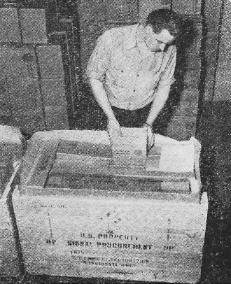
Final moisture-proof packing of one complete SCR 284-A unit,
containing all equipment for both vehicular and field equipment.
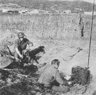
The SCR-284-A in actual field service in an active combat area.
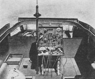
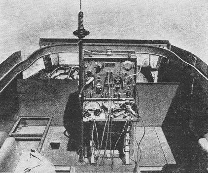
The receiver and transmitter unit (SCR-284-A) shown completely
mounted in half-track.
Posted June 23, 2021
|