|
Prior to phasing-based single
sideband generation circuits, a brute force filtering of the unwanted sideband and
carrier signals was required. Depending on how well the carrier was suppressed,
more than half the total signal power could be lost. According to author Jack Brown
in this "Commercial Aspects of Single-Sideband" article from a 1956 issue of
Radio & Television News magazine, it had only been since the mid 1940s
that wide-band audio-frequency phase-shift networks were even feasible. An ideal
implementation of a
single-sideband suppressed-carrier modulator
(SSB-SC) would result in 100% efficiency, but typical results are in the 80% range.
When I built my first SSB-SC modulator around 1990, it was by using discrete 90°
power dividers / couplers, sine and cosine local oscillator signals, and a pair
of matched mixers. An amplitude adjustment in the one of the paths (I and Q) allowed
adjustment for carrier cancellation. At the time there was not a selection of integrated
circuits available to do the job with a single part. Since then a plethora of such
ICs have appeared on the market that do the job much better than with discrete components.
See Part 1 in the May 1956 issue of Radio & Television News.
Commercial Aspects of Single-Sideband
Part 2. A discussion of single-sideband generation using either of two current
systems: filter or phase-shifting.
By Jack N. Brown, Engr., Barker & Williamson

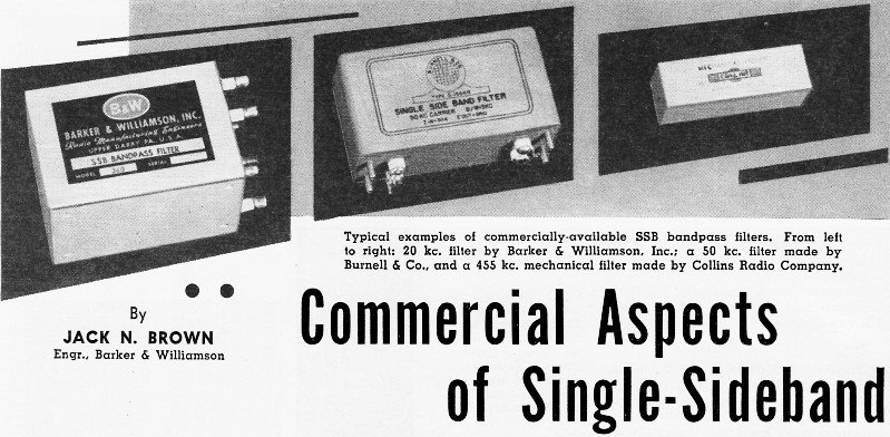
Typical examples of commercially-available SSB bandpass filters.
From left to right: 20 kc. filter by Barker & Williamson. Inc.; a 50 kc. filter
made by Burnell & Co., and a 455 kc. mechanical filter made by Collins Radio
Company.
In the first article of this series we dealt briefly with the theoretical system
gains of a single-sideband versus an AM system, the economic considerations involved
in converting an AM system to single-sideband, as well as some of the less extensive
technical considerations of single-sideband such as frequency stability requirements
and the choice of single-sideband generation systems. In this article the author
proposes to delve deeper into the method of single-sideband generation by the two
currently available systems.
The Filter System
The filter system of generation was the first one that was technically available
for use when single-sideband was under consideration. Since it was shown theoretically
that sidebands do exist about an amplitude-modulated carrier, it then became a problem
for the engineer to design satisfactory filters which could, by brute force, separate
one sideband of an AM signal from its adjacent sideband. If we consider that speech
frequencies on the order of 300 to 3000 cycles are necessary for satisfactory communication-type
speech systems, the filter problem then is to separate the sideband signals lying
either side of the carrier.
To the design engineer this means that the sideband filter must be able to discriminate
between signals that are a minimum of 600 cycles apart. For many years this filter
requirement could be met only by filters in the high audio or low radio frequency
spectrum. Until relatively recent years all sideband filter generation was at or
below 100 kc. Filters of the LC variety were in common use in the region of 15 to
60 kc. and quartz crystal lattice filters were used in the region of 50 to 100 kc.
These very satisfactorily divorced the two sidebands of the double-sideband suppressed-carrier
signal that had to be generated first. See Fig. 1 for a block diagram of a typical
filter-type single-sideband transmitter. In recent years improved techniques in
filters have made possible the manufacture of filters at higher frequencies than
previously considered feasible. It is now possible to build magnetostriction or
mechanical filters up to the region of approximately 500 kc. The construction of
crystal lattice filters up into the region of a few megacycles is more practicable.
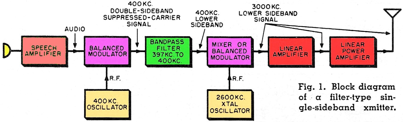
The block diagram of Fig. 1 uses what might be a typical filter in the low radio
frequency spectrum of approximately 400 kc. The speech signal is fed into the microphone
and amplified in the speech amplifier and thence goes into the balanced modulator.

Fig. 1 - Block diagram of a filter-type single-sideband transmitter.
The low-frequency carrier oscillator at 400 kc. also feeds an r.f. signal into
the balanced modulator. The balancing action of this modulator stage successfully
eliminates the carrier signal at its output yet under application of speech signals
at the microphone, a double-sideband suppressed-carrier signal is present at the
output of the balanced modulator. The sidebands thus generated lie symmetrically
either side of the 400 kc. r.f. carrier frequency. The identical sideband signals
are then fed into the sideband filter, the filter discriminates between the sideband
signals in that it passes the sideband signals lying to the low-frequency side of
400 kc. and attenuates the sideband lying just to the high-frequency side of the
400 kc. carrier frequency. At the output of the sideband filter we have a carrierless
single-sideband signal whose suppressed-carrier frequency is 400 kc. and whose intelligence
is contained in the 3 kc. spectrum just below 400 kc. The lower audio speech frequencies
will lie closest to the 400 kc. carrier frequency while the higher audio frequencies
are correspondingly farther away (to the low side) from the 400 kc. carrier frequency.
Our problem now is to translate the single-sideband signal existing at approximately
400 kc. up to a usable operating frequency of, for example, 3 mc. The single-sideband
signal is then fed into a mixer or balanced modulator stage into which is also fed
an r.f. voltage from a crystal controlled or stable v.f.o. source which is exactly
400 kc. removed from the desired output frequency. If operation is desired on 3
mc., for example, the oscillator frequency must be either 2600 kc. or 3400 kc. If
the 2600 kc. oscillator frequency is used and the 400 kc. lower sideband is heterodyned
with this oscillator frequency, a lower sideband signal with a suppressed carrier
frequency of 3 mc. will exist at the output of the high-frequency balanced modulator.
If the 3400 kc. oscillator frequency was chosen and the 400 kc. single-sideband
signal arithmetically subtracted, the result at 3 mc. would be an upper sideband
signal. A pencil, a piece of paper, and a couple of minutes will demonstrate the
reason for this. Use actual numbers for the sideband frequency existing for a 2000
cycle audio tone and a suppressed carrier frequency of 400 kc. This simple mathematical
manipulation is left to the reader. If the high-frequency mixer is actually a balanced
modulator, the oscillator frequency at either 2600 or 3400 kc. can be balanced out.
The tuned circuits following the high-frequency balanced modulator must successfully
discriminate between the sum-mixture of the sideband and oscillator frequency and
the difference-mixture of the same sideband and same oscillator frequency. If the
2600 kc. oscillator frequency was chosen, the tuned circuits following the balanced
modulator must pass the 3000 kc. lower sideband signal as well as attenuate the
upper sideband signal existing at 2600 - 400 or 2200 kc. In this part of the spectrum
two or three tuned circuits will accomplish this successfully. However, if operation
in the higher frequency part of the spectrum is contemplated, more tuned circuits
or a different heterodyning system must be used. It is often necessary to use multiple
steps in heterodyning a low-frequency generated single-side-band signal up to some
usable high frequency part of the spectrum, say 20 mc., for example.
It can be seen that we now have existing at a desired operating frequency a single-sideband,
either upper or lower, as the operator desires. The problem now is to amplify this
single-side-band signal to a high enough level to permit radiation by the antenna
system, The amplifier stage or stages following the last heterodyning stage must
be some class of linear amplifier. Linear amplifiers will be discussed in detail
later in this article.
The Phasing System
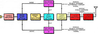
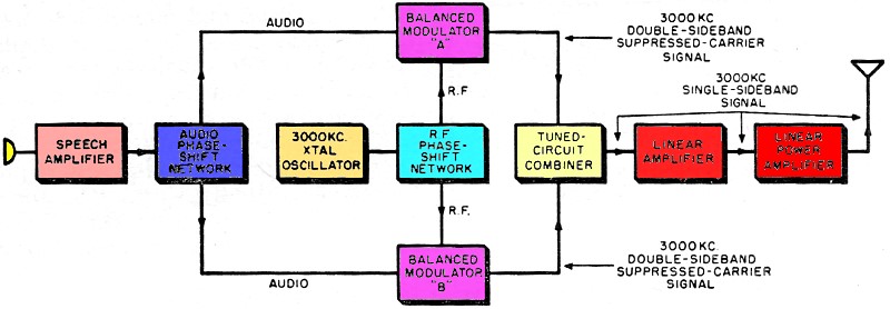
Fig. 2 - Block diagram of a "fundamental phasing" single-sideband
transmitter.
Generation of a single-sideband signal by the phase-shift method has been possible
only in recent years. It has only been since 1946 that it has been feasible to construct
wide-band audio-frequency phase-shift networks. The successful phase-shift generation
of an SSB signal places very strict requirements on certain critical parts of the
sideband generator. See Fig. 2. It can be seen in Fig. 2 that two different types
of phase-shift network are necessary. The audio-frequency voltages picked up by
the microphone are amplified in the speech amplifier and appear in the input to
the audio-frequency phase-shift network. This network must meet two very stringent
requirements. Throughout the audio-frequency range used (usually 300 to 3000 cps)
this network must yield two output audio voltages which are identical in amplitude
and frequency but which must differ by exactly 90° in phase relationship. See
Fig. 3 for a schematic of a typical audio network. The departure from exact equality
of the two output voltages or exact quadrature relationship in phase will cause
a deterioration of this generated SSB signal. The v.f.o. or crystal-oscillator signal
is fed into a radio-frequency phase-shift network which must fulfill exactly the
same conditions as that of the audio phase-shift network. The r.f. network must
give two equal output voltages whose phase relationship is exactly quadrature, that
is, they must be exactly 90° apart. Since the radio frequency involved is a single
frequency, the problem of constructing a practical r.f. phase-shift network to work
on a fixed frequency is comparatively simple. A simple combination of R, L, and
C can do this quite nicely. See Fig. 4. However, if operated on any frequency other
than that for which the r.f. network was designed and adjusted a deterioration of
the single-sideband signal will result.
The block diagram shown in Fig. 2 is for a "fundamental phasing generator." By
this is meant that the single-sideband signal is generated at the frequency of the
desired transmitter output. Thus it can be seen that for each frequency of operation
a different r.f. phase-shift network must be used. The dual output of the audio
phase-shift network feeds into two separate balanced modulators labeled "A" and
"B." The two separate r.f. output voltages from the radio-frequency phase-shift
network likewise feed into the previously mentioned "A" and "B" balanced modulators.
The r.f. and audio-frequency signals combine in each to produce at the individual
balanced modulator output a double-sideband suppressed-carrier signal. Thus at the
output of balanced modulator "A" there appears a double-sideband suppressed-carrier
signal with carrier frequency of 3000 kc., likewise, at balanced modulator "B" another
double-sideband suppressed-carrier signal appears also of 3000 kc., suppressed-carrier
frequency. These two double-sideband signals are identical in every respect except
that the instantaneous phase-shift relationship of one side-band in each balanced
modulator output is exactly 180° opposed.
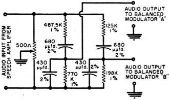
Fig. 3 - B & W's audio phase-shift network.
At the output of the two balanced modulators "A" and "B" the two sidebands that
are out-of-phase will cancel while the other remaining sideband signals will add
and reinforce each other at the output of the balanced modulators. Thus by careful
manipulation of the phase relationships of sideband signals involved it is possible
to successfully attenuate one sideband of an AM signal. With the fundamental frequency
SSB generating system if operation on other than the alignment frequency is desired
careful realignment of the r.f. phase-shift network is necessary to operate satisfactorily
on the new frequency. It has generally been found satisfactory to design a radio-frequency
phase-shift network that yields a constant r.f. 90° phase-shift between the
two output r.f. voltages for varying frequency input but the two amplitudes of the
individual outputs vary in direct proportion to the operating frequency. If a certain
design tolerance is permitted in the variation of operating frequency so as not
to degenerate the quality of the single-sideband signal, a certain frequency variation
about the design center frequency may be used. If we restrict the change in operating
frequency to ±2 1/2% of the operating design center frequency it will be
found that (all other phase-shift and amplitude relations in the single-side-band
generator being perfect) the unwanted single-sideband suppression will be degraded
to a value of 37 db. This value of 37 db is generally considered acceptable. However,
it must be remembered that all other phase-shift and amplitude regulations must
be perfect in order to get 37 db sideband attenuation.
In general, this will not be the case and further degradation of the sideband
suppression will result. For a commercial-type service where operation only on certain
fixed frequencies is contemplated, the fundamental phasing type single-sideband
generator would appear to have some merit. Since it is possible to build very stable
components, the r.f. phase-shift remains relatively constant with time and temperature
variations. It would appear that this would be a most economical method to use.
Where a number of fixed frequency channels are required in commercial service the
individual channel r.f. phase-shift networks could be made part of the channel selector
switch which would normally change the frequency control system of the basic transmitter.
It is also possible to build precision audio phase-shift networks to hold an angular
accuracy to considerably less than 1°. The fundamental phasing sideband generation
system would appear to be a "natural" for converting an existing AM transmitter
to single-sideband type transmission. See Fig. 5.
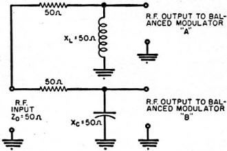
Fig. 4 - Radio-frequency phase-shift network.
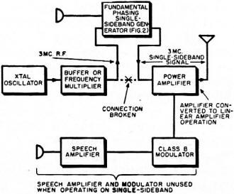
Fig. 5 - How an AM transmitter can be converted to SSB operation.
Refer to text.
The normal frequency control components and stages of the AM transmitter in question
are used to furnish the r.f. signal indicated in the block labeled "xtal. oscillator"
in Fig. 2. The r.f. from the exciter stages would be fed into the r.f. phase-shift
network and thence into the two "A" and "B" balanced modulators. It would appear
uneconomical to make general use of the audio-frequency equipment in an existing
AM transmitter since only one or two stages of audio amplification are necessary
to drive the precision audio phase-shift network also illustrated in Fig. 2. The
output of the dual balanced modulators after a stage or two of linear amplification
in the external single-sideband generator would then feed the single-sideband signal
back into the grid circuit of the existing AM transmitter. It would be necessary
to make appropriate changes in the AM transmitter final amplifier to insure that
it would operate as some form of linear amplifier rather than in its former class
C operation. This would necessitate readjusting the operating bias on the control
grid of the final amplifier to a value that would permit operation of the tube as
a class A, class AB1, class AB2 or class B linear amplifier.
The tube characteristic should be consulted for proper operating bias. If the transmitter
output tube is a tetrode the screen voltage applied must be stabilized by using
voltage regulation either of the vacuum-tube or gaseous-tube type. The converted
AM transmitter will perform satisfactorily as a single-sideband transmitter. The
normal AM speech amplifier and class B modulator stages will be unused and appropriate
measures can be taken to disable them to conserve power drain on the transmitter
power supplies. One manufacturer markets such a unit for converting amateur transmitters
to SSB if they fulfill certain minimum requirements. Admittedly this is for the
restricted range of the amateur bands, however, it would appear that the same techniques
would be quite usable for the commercial services where a given number of fixed-frequency
channels are used. This should be a very good interim method of obtaining single-sideband
without the pain of discarding existing AM equipment.
Linear Amplification
In the preceding discussion brief mention was made of linear amplifiers. This
is a subject which, in itself, could occupy many thousands of words and yet not
be satisfactorily covered. It is not the intention of the author to delve deeply
into the general subject of linear amplifiers. A linear amplifier is one whose output
is an amplified replica of the grid input signal. The most commonly encountered
linear amplifiers are the ordinary class A amplifiers in an audio system or the
r.f. amplifiers employed as r.f. stages in the front end of a receiver or the high
level modulator stages used in currently-operated AM equipment. The linear amplifiers
used in single-sideband amplification work on the same principle except that in
all cases tuned circuits or r.f. coupling devices are used as interstage and output
coupling units. Since a single-sideband signal once generated is made up of amplitude
variations, any amplification of the signal following generation must be of a linear
nature to faithfully reproduce all of the amplitude variations involved. If linear
amplification is not attained spurious adjacent channel signals are generated in
the amplifier circuits themselves creating unnecessary adjacent channel interference
to other services and contributing nothing as far as the intelligence transmitted
by the offending station. The most common causes of non-linear distortion in amplification
are: 1. Improper adjustment of operating bias on the grid of a linear amplifier;
2. Improper plate loading of the linear amplifier, and 3. Too large a driving signal
causing saturation of the operating characteristics.
Anyone or all of these factors will cause serious distortion products which will
cause adjacent channel interference. Several articles have appeared2,3,4
in recent technical literature which outlined the requirements and certain techniques
to be used in linear amplification.
Various Systems
From the preceding discussion it can be seen that the fundamental phasing generating
system is not feasible for general coverage of the high-frequency range. If general
or continuous cover-age of the 2 to 30 mc. high-frequency range is necessary it
would appear most reasonable to make use of heterodyning techniques in order to
cover the spectrum properly. This involves genera ting the single-sideband signal
by either the filter or the phasing system at some fixed frequency and by either
single or multiple heterodyning steps to cover the high-frequency communication
spectrum. Heterodyning a fixed-frequency, single-sideband signal to any other part
of the radio-frequency spectrum cannot be done without careful consideration of
the frequencies involved, the selectivity of the tuned circuits following the heterodyning
stage, and the possible combinations of the heterodyning frequencies. Spurious mixture
outputs are the result of heterodyning of the harmonics of the two signals being
fed into the mixer or balanced modulator stage. It is possible to have present at
or near the desired output frequency a spurious signal either c.w. in nature, or
a single-sideband signal of either upper or lower sideband. Very careful consideration
must be given to this matter in the initial design of any single-sideband equipment.
It can be seen that the one big advantage of the fundamental frequency generating
system, using the phasing technique, is that no spurious mixture products are encountered
since the single-sideband signal is generated at the fundamental output frequency.
The design engineer must then decide which system is most applicable to the particular
problem with which he is concerned. If the heterodyning system is to be used it
is suggested that the design engineer consult the spurious mixture product charts
published by Badessa5 and Eberhardt.6 These two articles will
give the design engineer some very handy tools for designing the heterodyning system
to be used. The author can not over-emphasize the importance of the design characteristics
that must be considered in a heterodyne system.
Problems of the Design Engineer
The single-sideband equipment design engineer is faced with varying and somewhat
difficult problems involving, in general, the following:
(1) Frequency stability. This would appear to be one of the most difficult problems
to solve particularly when the service to be rendered must be of the highest quality.
Where high quality continuously stable service is to be rendered, frequency stability
on the order of ±5 cps might possibly be required. When considered at a carrier
output frequency of 20 mc., this stability might be difficult to attain. It would
appear that some system of automatic frequency control or frequency synthesis would
be necessary. There are various methods of obtaining a frequency-synthesized master
frequency7. Good high-frequency quartz oscillating crystals are currently
available with an inherent stability on the order of 1 part in 10 per day. This
is assuming that the quartz crystal is pre-aged and in a temperature-controlled
oven. If operation below 10 mc. is contemplated, the frequency stability problem
assumes proportions of a somewhat minor nature. There are many services that do
not operate above 10 mc. and therefore the frequency stability problem is not as
severe as previously considered.
(2) A second problem facing the engineer would be the design of adequate sideband
generating filters. Conventional filter design can be used for filters from the
high audio frequencies through approximately 100 kc. using LC type networks. For
frequencies above 100 kc. it will probably be necessary to consider some means such
as quartz crystal filters, or magnetostriction or mechanical-type filters. There
are currently available on the commercial market filters of each type which might
be considered by the equipment design engineer. If the engineer wishes to design
a suitable single-sideband filter he must keep in mind that the slope or skirt selectivity
of the filter used must be extremely good so as to separate the low-frequency speech
components on one side of the carrier from the low-frequency speech components on
the other side of the carrier frequency. This means, in general, that the skirt
selectivity characteristic of the filter must drop at least 60 db in one kilocycle.
This is a rather strict requirement placed upon the filter but it is possible to
design and build filters to do this satisfactorily.
(3) The third problem that might confront the engineer is the design of suitable
audio- and radio-frequency phase-shift networks. It is suggested that the design
engineer consult the original paper by R. B. Dome8 as well as those by
Saraga9 and Luck10. The design engineer must select his parameters
carefully and make sure that he is considering the proper audio-frequency bandpass
to be transmitted. In general, the speech spectrum from 300 to 3000 cps is satisfactory
for the male voice in communication service. However, in other classes or higher
grades of commercial service it might be necessary to consider a wider band of audio
frequencies to be transmitted. This places stricter requirements on the audio phase-shift
network and makes the design procedure more complex.
(4) A fourth problem confronting the design engineer is one already mentioned,
this is the heterodyning system. The spurious mixture products that appear in the
heterodyning process can be of a very serious nature. If not carefully considered,
the spurious mixture products can cause interference to channels which might, conceivably,
be considerably removed from the desired operating frequency. Once a design is assumed
and a model built, the output should be carefully checked by a continuous-coverage
communications receiver loosely coupled to the generator output to determine if
spurious mixture products are being radiated.
(5) The fifth problem to be considered is that of proper linear amplification.
If a high quality single-side-band signal has been generated either by the filter
or the phasing system the signal can be seriously deteriorated by poor design and
operation of the linear amplifiers following the generator. It would be foolish
to generate a superior single-sideband signal and later cause it to deteriorate
by poor linear amplification. The final criterion of the single-sideband suppression
is, in most cases, the degree to which the amplifiers remain linear and do not generate
non-linear distortion products in the amplification system. The use of speech compression,
speech limiting, or an automatic gain control system is worth considering. The use
of negative feedback around the r.f. linear amplifiers is also worthwhile and has
been adopted commercially by at least one manufacturer." Grounded-grid amplifiers,
in themselves, provide a certain amount of negative feedback as an inherent part
of their amplification system and might well be worthy of consideration by the equipment
design engineer. The problems facing the SSB design engineer are difficult but not
insurmountable.
References
1. Barker &; Williamson, Inc., Upper Darby, Pa. (Model 51SB)
2. Lund, Rose & Young: "Amplifiers for Multichannel Single Sideband Radio
Transmitters," Proceedings of the I.R.E.; July, 1952
3. Bruene: "Linear Amplifiers for SSB Transmitters," Electronics, August , 1955
4. Reque: "Linear R.F. Amplifiers," QST, May, 1949
5. Badessa, R. S.: "Mixer Frequency Charts," Electronics, August, 1946
6. Ebrhardt, A. E.: "Spurious Response Chart," Tele-Tech, December 1952
7. Pappenfuss: "A Stable Master Oscillator," Electronics, December, 1950
8. Dome: "Wideband Phase Shift Networks," Electronics, December, 1946
9. Saraga: "The Design of Wide-Band Phase Splitting Networks," Proceedings of
the I.R.E., July, 1958
10. Luck, D. C.: "Properties of Some Wide-band Phase Splitting Networks," Proceedings
of the I.R.E., February, 1949
11. Collins Radio Co. (See Reference No.3)
(To be continued)
Posted June 10, 2019
|