|
It seems that creating almost
cartoonish-looking antenna arrays for the purpose of signal gain and directivity
are usually relegated to the domains of military and amateur radio practitioners,
but this article from a 1952 edition of Radio & Television News magazine was
done by the Channel Master
Laboratories television antenna company. Successfully mounting and phasing even
two antennas can be challenging, but in this case four Yagis were arrayed and tuned
for operation. Trying to make the system work over the entire 4 octave band that
is the VHF broadcast realm (54 MHz for channel 2 to 210 MHz for channel 13) would
be nearly impossible without extremely complicated mechanical and electrical design,
so the engineers satisfied themselves with one channel at a time and used an adjustable
spacing scheme to accommodate all 12 channels. Extensive guying and bracing was
required to withstand wind loads. My guess is this "Supermount" never made it to
the production phase.
Stacking Four Z-Matched Yagis
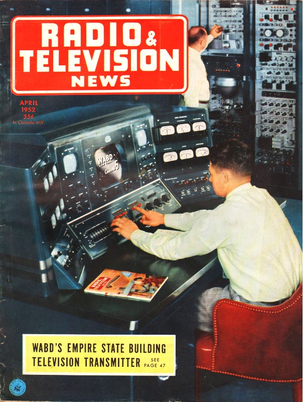
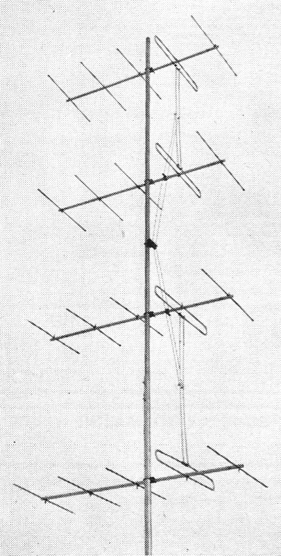
Fig. 1 - The new Channel Master "Supermount" antenna stacked
horizontally. The unit features adjustable structure.
By Harry Greenberg* and Harold Harris†
A new mechanical and electrical system incorporating a simple mounting arrangement
and a new impedance matching harness.
A practical system for stacking four Yagis by extending the principle of impedance
matching which led to the development of the "Z-Match" Yagi system has been developed
by Channel Master Laboratories. The resulting gains of over 14 db are the highest
yet attained in a practical television antenna.
The problem was of a dual nature because the mechanical problems were as formidable
as the electrical ones. For instance, if four-bay, half-wave vertical stacking were
attempted on Channel 2, the antenna array would require about 25 feet of unguyed
mast. On the other hand, on the high band, the length of masting required for four
bays is about 10 feet, which is a practical dimension. Therefore, a separate mechanical
approach was required on each band, although the electrical problem of phasing and
matching was the same. On the low band, the four-bay array was constructed by arranging
two stacked Yagis side by side. This arrangement was made practical by a new adjustable
structure made of heavy welded tubing (Fig. 1). This large mounting framework
was trade named the "Supermount,"
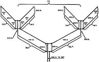
Fig. 2 - Operating principle of the four Z-matched Yagi
antennas.
The adjustable cross boom of the-"Supermount" provided for full-wave horizontal
spacing between the two stacked arrays. Since full-wave spacing was utilized, the
distance between the two stacked arrays ran up to 17 feet on Channel 2. The entire
structure was supported at the center. This meant that tremendous twisting torques
were developed under brisk winds. This torsion was excessive on most commercial
television towers because horizontal stacking narrows the directivity of the antenna
and makes it more sensitive to twisting. The twisting problem was solved by guying
the array at its outer extremities under each stacked Yagi. Guying at these points
also kept the guy wires out of the field of the antenna. These guy wires, in turn,
created a large downward thrust on the extended booms and this, in turn, was offset
by diagonal braces.
Since all of these operations had to be accomplished while assembling the entire
array from the top of a tower, the entire structure was designed in two parts so
that the spacing between stacked arrays could be adjusted for each channel and so
that the diagonal brace could be pivoted to fasten with a universal clamp at any
point of the tower. The cross booms are held in a section of tubing of larger diameter
so that the first Yagi of each pair can be put on, the connecting rods attached,
and then swung into the upper position by rotating the boom. Then the lower Yagi
is put on. The identical process is repeated for the other pair of Yagis. Before
discussing the electrical considerations in phasing and matching four Yagis, it
is interesting to note that the "Supermount" can be used for mounting stacked Yagis
of two different channels even though they require separate orientation.
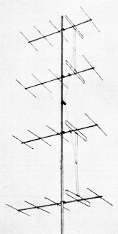
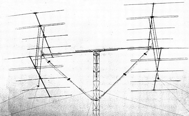
Fig. 3 - The "Supermount' antenna stacked vertically. Because
the unit is adjustable. several arrangements are possible.
In the article, "The Yagi Antenna" published in Radio & Television News,
October 1951, the problem of matching a two-bay Yagi to 300 ohm line was discussed.
A system, subsequently named the "Z-Match" system, was described. In this system,
the single Yagi uses a three-conductor fold and by wider spaced elements is designed
to accurately match 300 ohm line. The impedance is dropped to 200 ohms by taking
out the center bar in the folded dipole. The center bars from the two Yagis are
then used as the linear matching transformers and they step the 200 ohm impedance
up to 600 ohms. The two 600 ohm impedances in parallel total 300 ohms and match
the line accurately. It is two arrays of this description which are to be stacked
in four bays. From the following, it will be evident that an accurate two-bay impedance
of 300 ohms is necessary.
In the case of the high-band Yagi is, the four arrays were stacked vertically
with half-wave spacing between each bay (Fig. 3). On the low band, the two
half-wave stacked arrays were spaced a full wave apart. Since these dimensions made
the use of a quarter-wave transformer impossible, and since half wavelengths of
line do not transform impedances, two 3/4 wavelengths of line were used. This length
has the same impedance transforming properties as a quarter-wave line. That is,
the matching impedance is equal to the square root of the input impedance multiplied
by the output impedance or  . .
Therefore, the problem resolved itself into the following considerations. We
knew that in order for the feed point of the entire four-bay array to match 300
ohm line, each two-bay antenna had to present an impedance of 600 ohms. These two
600 ohm impedances in parallel equaled 300 ohms which was the required impedance.
We also knew that each two bay "Z-Match" array had an impedance of 300 ohms. The
problem then was to transform the 300 impedance of each two-bay Yagi to 600 ohms
through the 3/4, wave transformer. Substituting in the formula
we get the following:
 , or Zm =
425 ohms. In other words, a 3/4 wave line having a characteristic impedance of 425
ohms will tie the two stacked Yagis into one four-bay array with all impedances
matched to 300 ohms. , or Zm =
425 ohms. In other words, a 3/4 wave line having a characteristic impedance of 425
ohms will tie the two stacked Yagis into one four-bay array with all impedances
matched to 300 ohms.
The entire system is shown schematically (Fig. 2). Electrically, the system
is the same whether the stacking is vertical or horizontal. Special 425 ohm harnesses
were developed for each band. On the high band, a self-supporting open-wire system
was used. On the low band, a special wide-spaced 425 ohm ribbon type transmission
line was developed because ordinary open-wire line was difficult to support on the
boom structure.
* Chief Electronic Engineer, Channel Master Corp.
† Vice-president, Sales & Engineering, Channel Master Corp.
Posted March 14, 2022
(updated from original post on 12/30/2015)
|