|
October 1957 Radio & TV News
 [Table
of Contents] [Table
of Contents]
Wax nostalgic about and learn from the history of early
electronics. See articles from
Radio & Television News, published 1919-1959. All copyrights hereby
acknowledged.
|
Sure, you do it all the time,
but at some point either someone probably suggested to you and/or showed you how to clip substitute
components into a circuit in place of a suspected bad component while troubleshooting
or maybe during the design or tuning process. Miniature circuits of today pretty
much rule out using alligator clips to patch in a part, but sometimes it is possible
to use miniature "J" clip leads or even pin probes to make the connection long enough
to take a measurement. Since I do a fair amount of circuit work on other-than-RF
applications, I often find myself using short insulated, stranded wires with mini
alligator clips on each end to make connections. This "Substitution Jigs Speed Service"
article from a 1957 issue of Radio & TV News magazine has a few tips
for you.
Substitution Jigs Speed Service
By B. Van Sutphin
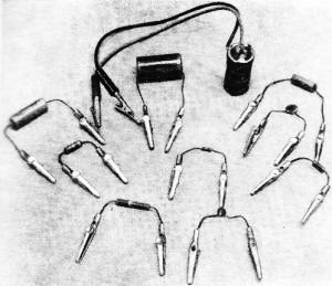
Fig.1 - Common, single-component jigs used in service, referred to in text.
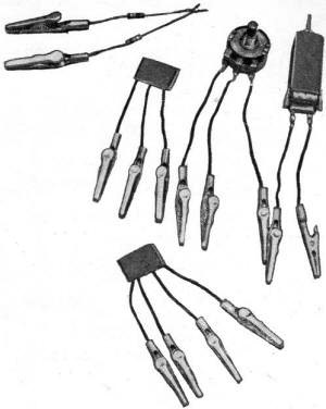
Fig. 2 - Clip leads can also be fixed to elaborate components such as potentiometers, i.f. cans, printed circuits.
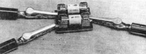
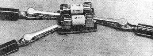
Fig. 3 - Two silicon rectifiers in holder can be hooked up in half-wave,
full-wave, doubler, or other configurations for power-supply tests.
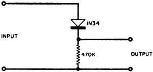
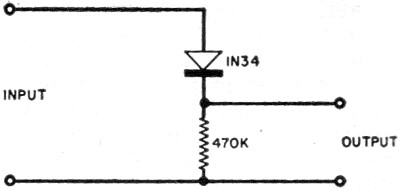
Fig. 4 - This detector jig provides an audio signal from a modulated generator
which does not have a separate audio jack.
Fig. 5 - Trace of flat band of a sweep generator, taken through detector
probe.
The use of clip leads for temporary test hook-ups can be extended to provide
even more time-saving.
In the service shop, the accent must be on convenience and speed. If time can
be saved, that means more income per hour of work.
Most shops keep a collection of clip leads for temporary connections to speaker
voice coils, phono motors, and other points. These are simply lengths of insulated
wire with alligator clips at each end. In addition, special jigs are often made
up for connection problems that come up again and again. Typical examples are jigs
to fit the speaker sockets of popular auto radios with leads to connect to the shop
test speaker and special jigs for feeding the sweep-generator output to a TV receiver.
This idea can be extended even further. Fig. 1 shows some single-part jigs
convenient in radio and TV servicing. Included are two common filter capacitors,
a special-value 1000-volt capacitor for testing in damper circuits, a general-purpose
600-volt test capacitor, two resistors of common value, and three low-value ceramic
capacitors for general-purpose testing. Although not shown in Fig. 1, a video-detector
diode jig is also convenient. The units shown are constructed by adding alligator
clips to each end of the individual parts. For maximum safety, insulated clips can
be used if they are available.
With a collection of these aids, part substitution is simply a matter of connecting
two clips. This system is much safer than trying to hold a part in place while watching
a TV screen and it is much simpler than "tacking" new parts in place with solder.
Think of the ease of substituting new parts when the customer asks for a quick estimate!
In most cases, substitution can be made by clipping the replacement directly
across the suspected part. Of course, this does not apply when the suspected defect
is a short in the original part. In those cases, you would have to disconnect one
side of the original part and then clip the new one in place, but even here some
time is saved.
As shown in Fig. 2, this idea can be carried further yet. Clips can be mounted
on potentiometers, i.f. transformers, and even complete printed circuits, provided
there are not too many leads. The "can" shown in Fig. 2 is a 4.5-megacycle
sound take-off coil common in many receivers. The printed circuit with three leads
is a vertical integrator network, complete with built-in blocking capacitor (Centralab
PC-101). The blocking capacitor is important so that the network can be used in
more receivers - this one can replace the original network whether it uses a blocking
capacitor or not, and whether it is a printed circuit or uses separate components.
In Fig. 2, the printed circuit with four leads is a complete network for
coupling the plate of a triode audio amplifier to the grid of an output stage.
If a number of these printed-circuit jigs are used, it is a good idea to draw
the schematic of each one on heavy paper and then paste it to the side of the printed
circuit. Use ink for drawing the schematic, and then coat the drawing with spray
plastic to protect it.
The twin-resistor jig at the upper left-hand portion of Fig. 2 is a pair
of 100,000-ohm resistors in series. This is for insertion in discriminator or ratio-detector
circuits during alignment. This is much simpler than soldering individual resistors
in place each time. "
The block-like device in Fig. 3 is a pair of silicon rectifiers (Sarkes
Tarzian M-500) in a standard holder. This unit can be used as a single half-wave
rectifier, a high-voltage half-wave rectifier (two rectifiers in series, useful
up to 260 volts), or as a two-section rectifier in a voltage doubler. It can be
used for temporary substitution in new sets using silicon rectifiers or in older
sets that originally used selenium rectifiers, whenever it becomes necessary, in
receivers of this type, to make checks on the operation of the power supply.
Fig. 4 shows a detector circuit for obtaining an audio signal from a signal
generator that does not have an audio output jack. Only two parts are used: a 1N34
crystal diode and a 470,000-ohm resistor. The unit is constructed just like the
twin-resistor jig shown in Fig. 2. Connect the signal-generator output to"
the input of the detector, set the signal generator to any convenient frequency,
and the audio signal will appear across the 470,000-ohm resistor. This audio signal
can then be fed to the circuit under test. Its strength can, be adjusted with the
r.f. attenuator on the signal generator.
A similar unit using a 1N82 high-frequency diode "and a 4700-ohm resistor is
handy for checking the outputof a sweep generator to be sure that it is reasonably
constant over a particular range. If the sweep generator does not have a terminating
resistor at the output of its cable, connect one having a resistance value equal
to the characteristic impedance of the output cable. This will prevent standing
waves from appearing because of possible impedance mismatching. Connect the sweep-generator
output to the detector input, and connect the scope input to the detector output
of the generator.
If the sweep-generator output is constant over the particular range, the trace
on the scope will be similar to that shown in Fig. 5. Any humps or dips in
the trace indicate that the sweep generator output is not constant over the range.
(Incidentally, it is well to check the detector on various ranges first with a sweep
generator known to have constant output. This is to prevent possible resonance effects
in the detector circuit from giving misleading results. This is particularly important
on the higher TV channels.)
The jigs described here are those the author has found most useful. Other service
technicians may think up their own to fit particular problems that come up again
and again. Technicians doing warranty work on a specific line of equipment will
probably find special units with parts that frequently fail very useful. Almost
any part can be put in a jig like this. Perhaps the only exceptions are parts used
in high-frequency circuits. For example, substitution of a new diode in a u.h.f.
converter circuit cannot be done this way. You still have to clip the leads and
solder the part in place.
Posted March 9, 2022
(updated from original post on 8/28/2014)
|