|
Here is a very nice introduction
/ refresher on RC (resistor | capacitor) and RL (resistor | inductor) time constants
and the waveforms they produce based on the applied signal and component values.
Author Tatz presented the information in a 1944 issue of Radio News magazine.
Only basic mathematical formulas are used, and the illustrations make the subject
of RC time constants understandable even without the equations. Don't be put off
by the vacuum tubes in Figure 1 because that oscillator schematic is only given
as a means for generating square wave and rectangular wave inputs to the RC and
RL test circuits, in case you don't have a signal generator handy. I remember in
college how much more meaningful the integrated and differentiated waveforms were
once Laplace transforms
were introduced for circuit analysis.
Transients and Time Constants
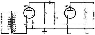
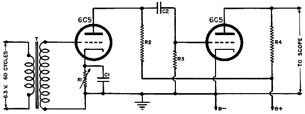
Fig. 1 - Circuit for generating either square or rectangular
waves.
C1 - 1-μfd., 400-v. tub. cond. C2
- 0.1-μfd., 400-v. tub. cond. R1 1-megohm carbon pot. R2
- 0.5-megohm, 1/2-w. res. R3 1-megohm, 1/2-w. res. R4
- 50,000-ohm, 1/2-w. res. T - Audio trans., 1:3 step-up

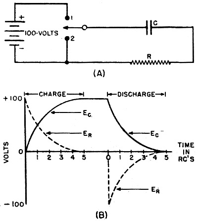
Fig. 2 - Charge and discharge effect of a condenser through
a resistance.
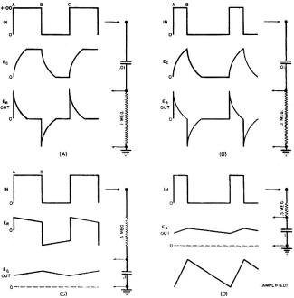
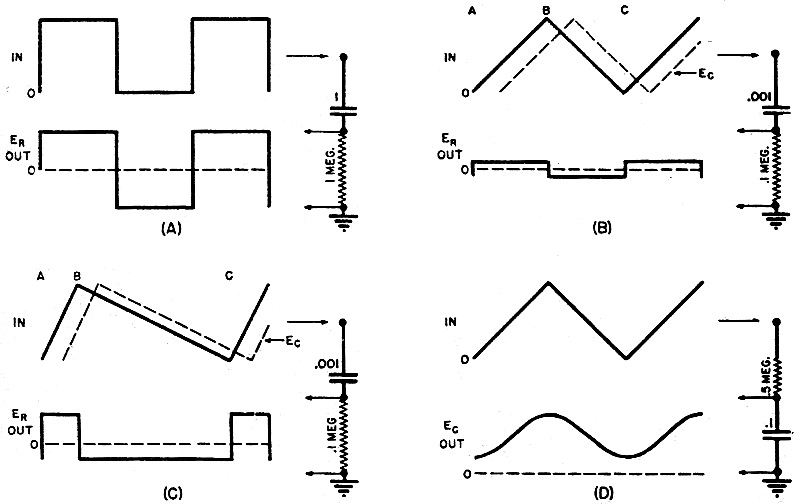
Fig. 3 - Wave shaping by means of RC distortion.

Fig. 4 - Additional applications of time constant circuits
to wave shapes.
By Abraham Tatz
An analysis of the effect of inductive and capacitive circuits having various
time constants upon sinusoidal and non-sinusoidal waveforms.
In testing the frequency response of amplifiers and transformers, square waves
have found great application because of their high harmonic content. The distortion
of the square wave in the output of the circuit tested yields a picture of the lack
of uniform response for the various frequencies involved among the harmonics. This
process of distortion to a new wave shape has now become a tool in the hands of
the research engineer in the new fields of electronics and television. The new wave
shapes needed for this work include narrow trigger pulses for synchronization, and
linear saw-tooth waves for sweep circuits. This desirable distortion of square waves
can be accomplished by a simple coupling unit of resistance and capacitance, or
resistance and inductance, in either case utilizing the frequency discriminating
quality of the reactance to change the shape of an applied voltage wave.
The original generation of a square, or rectangular waveform usually requires
a vacuum-tube circuit for the production of the original distortion and hence the
creation of the harmonics. A circuit that can be used to generate a symmetrical
square wave or an asymmetrical rectangular wave is shown in Fig. 1. The input
is a sine wave of sufficient amplitude (25 volts peak) to overdrive the first triode,
yielding a square wave on the plate when the cathode resistor R1 is set
at minimum. The second triode is an amplifier, also overdriven, which re-squares
the output of the first tube. R1 can be adjusted for symmetry of the
output square wave. When R1 is set at maximum the surge of tube current
through it on the positive signal swing accumulates a heavy charge on C1
sufficient to bias the tube for Class C operation. The output pulse is then amplified
by the second triode to yield a rectangular wave at this bias setting.
Transients in RC Circuits
To examine the effect of a resistance-capacitance circuit upon a square wave
it is helpful to regard the square wave as a sudden application of d.c. voltage
lasting for the duration limited by the positive alternation, and then a sudden
removal of the applied voltage. In Fig. 2, upon throwing the switch to position
1, the battery will force current through the circuit until the condenser is fully
charged to 100 volts. The charging of the condenser is not instantaneous, but takes
place in a measurable time, which is lengthened by an increase in the size of either
R or C. The formula for the charging curve of condenser voltage is
Ec
= Ea (1 - (1/et/RC)
where Ea is the applied d.c., t is in seconds, R in ohms, C in farads,
and e is a mathematical constant, 2.718. The formula yields the following information:
1) At initial time t = 0, Ec equals zero.
2) At time t = RC seconds, Ec = 63% of Ea. This time (RC
seconds) is called the time constant of the circuit, the product of Rand C, and
is defined as the time required for the condenser to acquire 63% of the applied
d.c. voltage.
3) At time t = 5 RC the condenser voltage practically reaches the applied voltage.
4) The charging curve is linear up to the time t = 0.3 RC, or 30% of the first
time constant.
5) The initial slope is such that the condenser would be fully charged in one
RC if the initial charging rate had been maintained.
During this charging time the resistor voltage, initially 100 volts because of
the heavy charging current, drops to zero in 5 RC time constants, when current flow
ceases because the condenser is fully charged. Er drops 63% in the first
time constant.
Upon throwing the switch to position 2 the condenser will discharge, taking five
time constants to do so. The discharge curve follows the formula
Ec
= Ea/et/RC
During the discharge the resistor voltage is in the opposite direction because
of reversed current flow. Here Er is initially negative 100 volts and
falls back to zero in 5 RC's, the end of the discharge.
Distortion by Time Constants
Now consider the square wave of Fig. 3a. It shoots from zero to 100 volts
and back, much as the plate voltage wave of a triode driven to cut-off and saturation.
Its frequency is 50 cycles per second, and the time between points A and B, the
duration of a half-cycle of positive d.c. voltage, is 0.01 second or 10,000 microseconds.
The circuit to which the square wave is applied has a time constant of 1,000 microseconds
(100,000 ohms times 0.01 μfd.). The condenser becomes fully charged in 5 RC's,
halfway between A and B, and fully discharged halfway between Band C. Note that
the condenser wave follows the applied square wave but lags behind it. The resistor
voltage, always the difference between the applied voltage and the condenser voltage,
is a positive peaked wave between A and B (condenser charging) and a negative peaked
wave between Band C (condenser discharging). At all times
Ea
= Er + Ec whether E. is 100
volts or zero. The resistor voltage is pure a.c., equal areas each side of the zero
axis, whereas the condenser wave is all above the zero axis.
The time constant of Fig. 3a is termed "short," allowing the condenser a
full charge or discharge within the time of an alternation. The resistor wave is
the useful output, finding its application as a trigger pulse. Note that the peaks
can be made more narrow by using a shorter time constant. A time constant is short
only in relation to the frequency of the applied wave. When the resistor voltage
is obtained as output from an RC circuit of short time constant the process is called
"differentiation," and in this case distorts a square wave into a peaked wave.
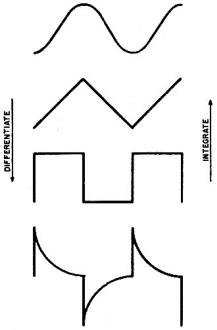
Fig. 5 - Wave shapes shown according to their harmonic constant.
The distortion in the output is due to poor low frequency response. The square
wave has an infinite number of odd harmonics, sine waves whose frequencies are odd
multiples of the fundamental fifty cycles per second. The highest frequency harmonics
cause the wave shape to be further removed from the appearance of the fundamental
sine wave. The reactance of the condenser in the differentiating circuit of Fig.
3a is greatest for the low frequency harmonics, causing the output across the resistor
to have an exaggerated component of high frequency harmonics. Thus, the peaked wave
is further removed from the sinusoidal appearance than the square wave.
The rectangular wave of Fig. 3b can be differentiated by the same time constant,
resulting in the peaked wave shown. Here the time constant must be short enough
to allow the condenser to become fully charged within the narrow portion of the
applied wave. For example, if the time between A and B is less than 5,000 microseconds
the time constant must be shorter than the one used in Fig. 3b to obtain a
peaked wave output.
When the square wave is applied to a circuit whose time constant is relatively
long, never allowing the condenser to become fully charged or discharged, distortion
can result in a useful voltage across the condenser. This process is called "integration"
and is illustrated in Fig. 3c. Here the fifty cycles per second square wave
is applied to a time constant of 50,000 microseconds. The time between A and B is
merely two tenths of one time constant, so the condenser voltage rises and falls
only slightly, and always within the linear portion of its charging or discharging
curve. The condenser output is called a triangular wave, whose operating axis is
the same as the axis of the input square wave, namely fifty volts. Several cycles
after it starts, the triangle settles to a fluctuation between 45 volts and 55 volts.
This amplitude could be increased by making the time constant smaller, but the wave
might then become nonlinear, especially since the discharge path is usually through
a heavily conducting tube of low resistance.
Examining the output triangle in the light of harmonic content of the input square
wave, it is seen that the condenser voltage is greatest for the lowest harmonic
frequencies. Hence the output contains a smaller proportion of high frequency harmonics,
resulting in a wave more nearly approximating the sinusoidal appearance.
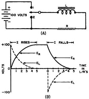
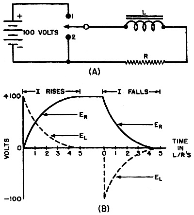
Fig. 6 - The rise and fall of a current through an inductor
as the potential is momentarily turned on or off.
The rectangular wave may be similarly integrated by the same time constant circuit
(Fig. 3d), resulting in a sawtooth wave of condenser voltage. This is the most
useful process of integration, yielding a voltage wave form used as a linear sweep
for deflection of the beam in a cathode-ray tube. Note that neither portion of the
saw-tooth is an instantaneous "fly-back," necessitating a blanking circuit to light
up the tube during only the sweep time. The great advantage of this sweep circuit
is that its frequency is rigidly controlled by the input wave being integrated.
Further Applications of BC Circuits
When the triangular wave is obtained in Fig. 3c, the resistor voltage wave
is a somewhat distorted square wave. The sides are steep, but the positive portion
falls off as the condenser charges up, and the negative portion falls off to the
extent that the condenser discharges within the time of one alternation. If the
time constant is made very long the triangle will become of negligible amplitude,
and the resistor voltage will be substantially square. This long time constant circuit
has application as the coupling circuit of Fig. 4a. Here the time constant
of one million microseconds yields an output resistor wave which is a replica of
the input. This coupling circuit is used to pass any harmonic wave with a minimum
of distortion. The reactance of the condenser is small for practically all harmonics,
avoiding distortion as the wave shape is coupled to a succeeding stage of amplification.

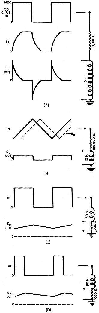
Fig. 7 - Wave shaping by means of L/R circuits. (A) By applying
a 50 cycles per second square wave. the time constant is short for it allows the
current to reach a final steady value within the time 1/2 cycle. Distortion of the
square wave into the peaked wave is due to the loss of low-frequency harmonics.
(B) By applying a triangular wave to the L/R circuit, the output will be a square
wave. (C) By applying a square wave to the circuit whose time constant is 50.000
microseconds, the output across the resistor is a triangular wave. (D) Saw-tooth
wave is obtained from the application of a rectangular wave.
The triangular wave can be differentiated by using the short time constant circuit
of 100 microseconds in Fig. 4b. Here the voltage across the 0.001 μfd. condenser
is another triangle, following the applied voltage very closely and always lagging
it. Between times A and B the resistor voltage
(Er = Ea
- Ec) is a constant positive value between times B and C the resistor
voltage is a constant negative value. Hence the output Er is an a.c.
square wave. The constant rate of change of applied voltage causes a steady current
to flow through the resistor during charging, and a steady current flow in the opposite
direction during the discharging time.
The same time constant may be used to differentiate the sawtooth wave (Fig. 4c).
The resistor output is a rectangular wave whose positive portion is of greater amplitude
because the slope of the sawtooth portion which produced it, A to B, is steeper
than the slope from B to C.
The processes of differentiating and integrating will change the. shape of any
input wave containing harmonics. For example, the triangular wave will be integrated
by the circuit of Fig. 4d. The condenser output is smoothed out as compared
to the input and because of the further removal of high frequency harmonics, has
very nearly the appearance of a sine wave. However, it still contains harmonics,
and is called a parabolic wave. Upon being differentiated this wave would yield
a triangle, whereas a pure sine wave, containing no harmonics against which the
reactance may discriminate, would yield another sine wave of diminished amplitude.
The integration of a saw-tooth wave, just as in Fig. 4d, would result in a
parabolic wave which is as symmetrical. Mathematically, it is said that an infinite
number of integrations of a harmonic wave will yield a sine wave. Practically, further
integrations approach a sine wave.
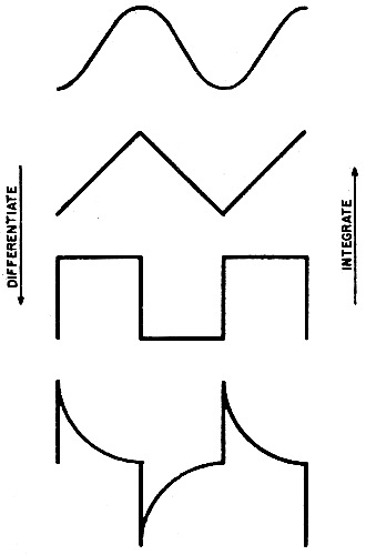
As a summary of these processes of distortion the chart of Fig. 5 shows
the interrelation of differentiation and integration. Note that two successive opposite
operations result in cancellation of the distortion. For example, the square wave
differentiated yields a peaked wave; the peaked wave integrated yields a square
wave of the same frequency. Actually, the new square waves usually will not be as
perfectly formed as the original unless the peaks are very narrow, but it does work.
It must be pointed out that each operation of wave shaping by distortion involves
a loss of amplitude in the output. Therefore, a string of successive differentiations
or integrations will require intermediate amplification, using a Class A amplifier.
Inductive Reactance for Wave Shaping
Just as the reactance of the condenser in a resistance-capacitance circuit can
produce desirable distortion effects upon a wave of high harmonic content, so can
the reactance of a coil in a circuit of inductance and resistance yield analogous
results for wave shaping. The previous discussion of differentiating and integrating
can be applied to this inductive circuit by deriving the definition of a time constant
with the same introductory example of a sudden application of a battery and a sudden
removal of the d.c. voltage. In Fig. 6 the closing of switch number 1 will
allow current to flow in the circuit. The back voltage induced in the coil by the
sudden current change prevents the current from rising instantaneously. Instead
it rises to its full value, 2 ma. (assuming no coil resistance) along the curve
shown. The curve is therefore a picture of the resistor voltage in the circuit.
The formula for this rise of resistor voltage is:
Er
= Ea [1-(1/eRt/L)]
where Ea is .the battery voltage applied, R is in ohms, L in Henries,
t in seconds, and e is a mathematical constant, 2.718.
Analysis of this formula yields the following information:
1) At time t = 0, Er = 0
2) At time t = L/R, = 63% of Ea
3) At time t = 5(L/R), Er practically equals Ea
The term L/R is the time constant of the circuit, defined as the time in seconds
for the current to reach 63% of its total possible rise toward a steady state. Here
again five time constants are required for a steady state to be reached.
The coil voltage EL is always the difference between the applied voltage
and the resistor voltage. It is initially 100 volts, and becomes zero after five
time constants. Remember that a coil voltage depends only upon changes in current.
Initially, the current change is greatest; therefore EL is greatest.
After five time constants the circuit has become steady and EL becomes
zero.
Closing switch 2 will cause the current in the circuit to die out. Again the
decay is not instantaneous, but requires five time constants for Er to
become zero. The sudden change to a decreasing current puts a voltage across the
coil of opposite polarity because the change is in the opposite direction. EL
becomes zero when the current finally becomes a steady zero value. The formula for
this decay is
EQUATION HERE
The time constant for this circuit is L in henries divided by R in ohms, with
the answer in seconds. Increasing the size of the inductance in the circuit of Fig.
6 will increase the time for the current to become a steady 2 ma. Keeping L constant,
decreasing R to 25,000 ohms will cause more time to be taken for the current to
reach its higher final value, 4 ma. Hence a time constant is made long by a large
L and a small R.
Wave Shaping Application of L/R Circuits
The fifty cycles per second square wave may now be applied to the circuit of
Fig. 7a. Here the time constant of 1,000 microseconds is short, for it allows
the resistor voltage to reach a final steady value within the time of one-half cycle.
The coil voltage is a peaked wave, a.c. This circuit is differentiating, yielding
the same output wave shape as the differentiating RC circuit. Distortion of the
square wave into the peaked wave is due to the loss of low frequency harmonics,
for these low frequencies will meet less coil reactance and will yield a smaller
coil voltage as compared to the high frequency output response. The rectangular
wave used in Fig. 3b can be applied to the same L/R circuit used above, yielding
peaked waves across the coil.
Since the circuit differentiates, it might be expected that a triangular wave
applied to it would yield a square wave across the coil. This is true, and is shown
in Fig. 7b. Note that the current wave, Er follows the applied triangle
closely but always lags it. A current lag is natural to an inductive circuit. Similarly,
the sawtooth wave of Fig. 4c, differentiated by the L/R circuit above, will
result in a rectangular voltage across the coil.
It will be remembered that integration, passing from a square wave to a triangle,
involves the use of a long time constant. A long L/R time constant needs a large
inductance and small resistance. The time constant must be sufficiently long to
allow only the linear portion of the rise and fall of resistor voltage to take effect.
When the square wave is applied to the circuit of Fig. 7c, whose time constant
is 50,000 microseconds, the output across the resistor is a triangular wave. Here
the high frequency harmonics are blocked from the output, leaving the low harmonics
to make up the triangle, the next step toward a sine wave. The rectangular wave
of Fig. 7d results in a sawtooth resistor wave, after integration by the same
long time constant.
Conclusions
Although wave shaping can be produced by either an RC or L/R circuit, several
important differences exist. The principal. advantages of the RC circuit are:
1) It is simpler, lighter and cheaper, therefore more prevalent.
2) The differentiating circuit can be used as coupling between two vacuum tube
stages, because the input condenser effectively blocks the d.c. voltage of a previous
tube from the succeeding grid circuit.
3) The differentiating RC circuit automatically insures a low impedance output
across the resistor, which can be made small for a shorter time constant.
4) The integrating circuit insures a high impedance output because the output
contains mostly the low harmonic frequencies across the condenser.
The L/R circuit enjoys the following advantages:
1) The differentiating circuit yields a high impedance output, only the higher
frequencies predominating across the coil output.
2) The integrating circuit results in a low impedance output, for this output
is taken across a resistor whose value is relatively small.
3) The principal advantage of the L/R circuit is that the triangular or sawtooth
wave obtained in the output of the integrating circuit is a resistor voltage, hence
a linear change in current. This linear rise or fall of current finds its greatest
application in magnetic sweep circuits using coils as the mechanism to deflect the
electron beam of a cathode-ray tube. This linear change in current guarantees a
linear change in the magnetic field deflecting the electron beam.
Posted June 28, 2021
|