|
In 1958, most people were not
accustomed to seeing the now-familiar maps plotting sinusoidal courses of satellites
across the face of the earth (a la Figure 1). It had only been in October of
the previous year that any object other than the moon was in orbit around our home
planet - that was U.S.S.R.'s Sputnik. Just as people of all ages and all backgrounds enthusiastically
joined in the newfangled phenomenon of aeroplanes after the Wright Brothers flew
their fragile craft at
Kitty Hawk, electronics communications and scientists worldwide
hopped aboard the satellite train (so to speak). This article from a 1958 issue
of Radio & TV News magazine provided insight into the construction
and flight characteristics of early U.S. satellites, and offered advice on how to
participate in the ongoing
International Geophysical Year (IGY) research effort by tuning in and reporting
your signal reception characteristics. Activity was not just the domain of operators
with sophisticated equipment, as the author outlines. To wit, "Signals from these
vehicles can be received by radio amateurs, hi-fi enthusiasts, or electronic technicians
without great difficulty." See "Magnetometer at Work in Outer Space."
Receiving U.S. Satellite Signals
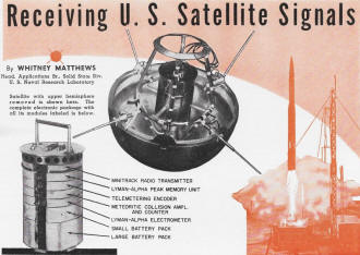
Satellite with upper hemisphere removed is shown here. The complete
electronic package with all its modules labeled is below.
By Whitney Matthews
Head, Applications Br., Solid Stale Div.
U. S. Naval Research Laboratory
The complete, authoritative story about the radio signals that the U. S. satellite
will broadcast.
Electronic technicians and hobbyists have an opportunity to make valuable contributions
to the scientific effort of the current International Geophysical Year. Plans for
launching instrumented artificial earth satellites have been announced by the United
States and the U.S.S.R. Signals from these vehicles can be received by radio amateurs,
hi-fi enthusiasts, or electronic technicians without great difficulty. Participation
of amateur observers would make available potential sources of valuable data which
would be prohibitively costly by means of primary recording stations.
Editor's Note: As we go to press the Army, as
was expected, has launched the "Explorer," the first U. S. satellite. The fully
instrumented satellite described here and shown on our cover is part of the Navy's
Vanguard project and is scheduled to go up in March. Much of the material contained
in this article applies to any of the U. S. satellites.
Not all of the satellites to be launched by the United States will provide continuous
transmission of scientific data. Early satellites may be placed in orbit as a part
of the launching vehicle test program. These possible early satellites would carry
unmodulated radio transmitting equipment intended primarily for radio tracking.
While not regarded as true instrumented satellites, they would be capable of providing
temperature information by accurate calibration and measurement of transmission
frequencies. Several designs of fully instrumented scientific satellites are being
prepared which will carry aloft, in succession, various combinations of scientific
instruments. As presently planned, the first two instrumented satellites to be launched
will provide continuous transmission of scientific data. It is these which would
be of most interest to amateur observers. Designs for later launching will provide
data transmission only when initiated by powerful ground transmitters. This technique
is used where power required by scientific instruments prohibits continuous transmission
or where it is necessary to play back and erase information recorded on magnetic
tape. Amateur observers can participate in collecting the intermittently transmitted
data only when located sufficiently close to a primary recording station to receive
signals when data is being transmitted.
Receiving Satellite Signals
The U. S. satellite will be launched from the Patrick Air Force Base at Cape
Canaveral in Florida. The satellite will circle the earth approximately once each
90 minutes. The plane of the orbit will make an angle of approximately 35° with
respect to the equatorial plane of the earth. Due to the rotation of the earth,
each successive orbit will receive an apparent shift westward of about 1200 miles.
The general character of the path of the satellite over the surface of the earth
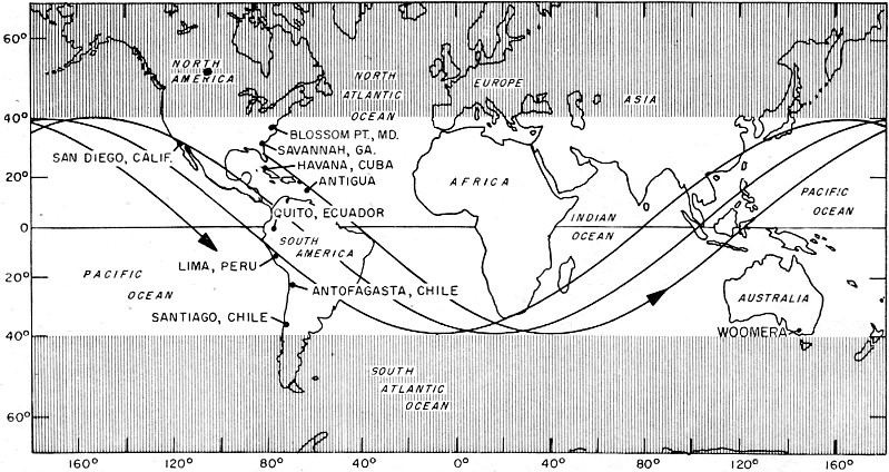
is shown in Fig. 1. Eventually the satellite will rather thoroughly traverse
the unshaded portion which represents nearly two thirds of the earth's surface area.
Near overhead transits of the satellite would thus be available to observers between
35° N and 35° S latitudes. Reception of signals outside this zone would
be determined by receiver sensitivity, antenna gain, and height of the satellite
above the earth. The orbit of the satellite is expected to be elliptical with altitudes
between 200 and 1500 miles.
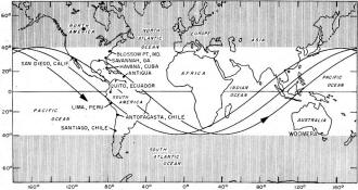
Fig. 1 - Some typical paths of artificial earth satellite
over the earth's surface.
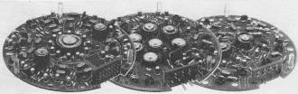
Fig. 2 - Satellite airborne telemetry encoder is at left.
Center unit is the meteoritic collision electronics with its amplifier and three
decimal digit counter. Unit at right is Lyman-alpha peak memory electronics including
orbital switch for reset once each orbit. Circuits are printed and extensive use
is made of transistors and magnetic amplifier coils. Units later covered with plastic
foam.
Provision for an adequate number of official recording stations to permit continuous
radio reception of satellite signals would be prohibitively costly. Primary recording
station locations are also shown in Fig. 1. A chain of stations is located
roughly along the 75th meridian down the east coast of the United States and the
west coast of South America. These stations provide a "picket fence" coverage which
the satellite must cross once each orbit. Two stations at Antigua, B.W.I. and San
Diego, California provide data early in and before completion of the first orbit.
One additional station at Woomera, Australia will provide frequent data at approximately
half orbital periods from other stations for the benefit of scientific experimenters.
Orbital parameters will be calculated from tracking data and made available to news
wire services. Contact with local newspapers, television or radio stations should
provide adequate information to permit amateur observers to know when to seek these
signals, Possibilities of visual observation of the satellite are limited to times
just before dawn or after dusk. The sun must be sufficiently below the horizon to
provide a dark sky yet sufficiently near to illuminate the satellite.
All scientific data will be transmitted by means of the "Minitrack" radio tracking
transmitter in the satellite. This transistorized, crystal-controlled transmitter
operates on a carrier frequency of 108.00 megacycles and is amplitude modulated
(AM) for data transmission. Peak operating power is about 100 milliwatts with 100%
modulation. Batteries carried by the satellite are expected to provide between three
and four weeks' active life. Airborne telemetry equipment is used to accept inputs
from the various scientific instruments and combine them into a single coded electrical
signal for transmission to the ground receiving stations.
Telemetry signal frequency components are in the audio frequency range and within
the recording capability of many high-fidelity home magnetic tape recorders. Maximum
frequencies of 15 kc. are used with signals rarely exceeding 12.5 kc. Two alternatives
are. available to persons not now having equipment to receive 108-mega-cycle AM
signals who wish to observe the satellite with their present equipment. Converters
are available or can be built by owners of communications type receivers. This method
offers the advantage of being able to use a beat-frequency oscillator to detect
passage of a satellite transmitting an unmodulated carrier. The second method requires
the addition of a simple AM detector circuit to a high-fidelity FM tuner. Commercially
available antennas designed for fringe area reception of FM broadcast signals should
provide ample gain for all but the most unfavorable reception conditions. Desirable
mounting of such an antenna would be in a generally skyward direction for latitudes
of 35° or less. Simple means could be provided for rotation of the antenna in
a direction to permit adjustment in advance for best reception of the next anticipated
transit.

This Month's Cover
The top half of the first fully instrumented U. S. satellite is carefully being
put into place. The 20-inch, 21.5-pound shiny ball will then be mounted within the
nose of the three-stage Vanguard rocket, shown blasting off on our cover. The rocket
is then expected to rise vertically at first and then gently turn in the direction
of its planned orbit. After successive burnout of the three stages, the tiny ball
should be hurtling around the earth at about 18,000 miles per hour, (Photos: U.
S. Naval Research Laboratory.)
Many of the scientific phenomena to be studied occur infrequently and at random.
These very facts prevent their systematic study by high-altitude research rockets.
Most desirable would be the occurrence of one of these events as the satellite signal
was being recorded at a primary receiving station. Such an observation would provide
a detailed record of instantaneous measurements as a function of absolute time.
Although possible, unfortunately the chances for an official receiving station to
record such an event are quite remote. An adequate number of properly located amateur
observers would make certain the availability of the desired records. Airborne equipment
will include memory devices for storing a limited amount of information concerning
these events for later transmission to official ground stations. These signals will
provide meager data on all such events viewed by satellite instruments but will
be far less informative than a properly made amateur recording obtained during the
event itself.
Recordings of amateur observers offer many possibilities of obtaining valuable
data other than observation of specific events. This is particularly true of data
obtained during the early life of a satellite. Obviously such data would be of utmost
value in case of a short active life of a satellite or any of its scientific experiments.
Such records would also be of value in case of errors in the predicted rate at which
phenomena being studied are expected to occur. Details regarding potential value
of amateur recordings will be presented later in the discussion of each experiment.
The Lyman-Alpha Satellite
One of the first fully instrumented scientific satellites planned for launching
by the United States will be devoted to two general types of measurements. One group
of measurements will study ultraviolet radiation from the sun in the region of the
solar spectrum known as Lyman-alpha. The second group of experiments designed to
study the satellite environment includes measurement of temperatures and various
types of information relative to collision between the satellite and small particles
(micrometeorites) in space. Equipment in the satellite will include a telemetry
encoder system. This equipment converts measurements made by the various airborne
instruments into a single signal for transmission to ground receiving stations.
The desired scientific information may be extracted from the received signal by
appropriate decoding.
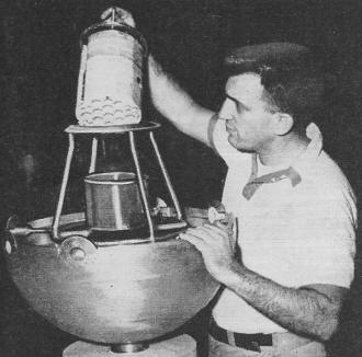
Fig. 3 - Here the entire electronics package is being installed
in the satellite. The electronic circuits are encased in a foam-in-place plastic
material.

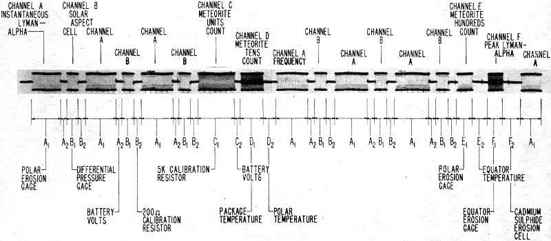
Fig. 4 - Typical Lyman-alpha satellite scientific telemetry
signal with all components of signal properly labeled.
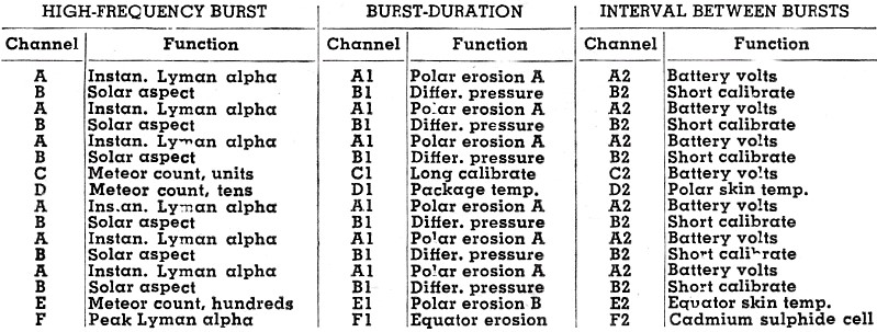
All information will be transmitted in the form of a series of high-frequency
(5 to 15 kc.) bursts carrying information on the frequency of these bursts, time
duration of each burst, and the time interval between bursts. Thus three information
channels are associated with each burst. Each frame or scan of all information channels
will consist of a sequence of sixteen such bursts for a basically 48-channel telemetry
system. The airborne telemetry encoder system used to produce these signals is shown
in Fig. 2. This unit is 5 1/2 inches in diameter, 3/4,-inch high, and weighs
about 3 1/2 ounces. It operates on 2.7 volts with a current drain of 3 to 4 milliamperes.
A new frame will begin immediately upon completion of each scan. Thus the exact
scanning rate will be a variable quantity determined by the values of input signals
which control burst duration and spacings. Signal values are expected to lie in
a range which provides three to four frames of telemetered data per second.
Of the measurements being made, some will undergo only insignificant short time
changes while others will be changing rapidly with time. For example, outer shell
temperatures will rise slowly as the satellite heats up when in sunlight and slowly
drop as the shell cools when in the earth's shadow. Thus, temperature changes during
one telemetry frame are of no great importance. On the other hand, measurements
of inputs such as the Lyman-alpha radiation do undergo significant changes during
a single telemetry frame. For this reason, several channels in each frame are devoted
to frequent repetition of these rapidly changing signals. Such signals are also
transmitted as a burst frequency to permit measurement of changes during the burst
interval.
An oscillogram of a complete typical telemetry frame is shown in Fig. 4.
Photographic resolution at the scanning rate used to present a full frame does not
permit distinction between cycles in each high-frequency burst. This oscillogram,
together with Table 1, will permit ample description of channel assignments
to permit amateur observers to seek out any desired signal for study. It will be
noted that all channels carrying information in the form of the burst frequency
are identified by a single letter. Channels whose data is presented as a burst duration
are designated by a letter followed by the numeral 1. Similarly information contained
in a burst spacing carries a letter identification followed by the numeral 2.
Each telemetry frame may be conveniently regarded as being divided into two sequences
of eight high-frequency bursts each. Each such half frame is distinguished by six
initial bursts containing an alternate rhythmic repetition of long and short bursts
carrying data on instantaneous solar Lyman-alpha radiation and solar aspect (orientation
of the satellite with respect to the sun). Thus each half frame can be seen to start
with the burst channel sequence A-B-A-B-A-B in Fig. 4 or Table 1. Identification
of these channels is relatively easy in any display medium whether it be audible
listening, oscillographic presentation, or photographic reproduction. The remaining
two high-frequency bursts in each half-frame scan will carry data readout of satellite
memory units. The two final bursts of successive half-frames will thus alternately
present information on (1) units digit and tens digit of the cumulative meteoritic
collision count (channels C and D) or (2) hundreds digit of the meteoritic collision
count and orbital peak value of solar Lyman-alpha radiation.

Table 1 - Telemetry channel assignments for Lyman-alpha-environmental
satellite.
Positive identification of alternate half-frames is provided by appropriate control
of burst and spacing durations. Thus the duration of the meteoritic collision count
units digit burst (channel C) is used to present the long calibration channel (C1).
This burst duration remains essentially unchanged and is always of greater duration
than any other burst. This long calibration channel is followed immediately by the
shortest burst spacing in the frame (channel C2). This shortest burst spacing monitors
the telemetry battery voltage. This identification of the telemetry signal half-frames
is evident from an examination of Fig. 4. The long calibration channel C1 in
the first half-frame is obviously longer than its counterpart channel E1 in the
second half-frame. Similarly the succeeding channel C2 is much shorter than is channel
E2.
Methods used by amateur observers to study records made will be determined, to
a great extent, by the equipment available. Experience has shown that, with practice,
a simple listening test can reveal valuable information. Listening tests are greatly
enhanced when original recordings are made at a high tape speed and played back
at a lower speed. This technique reduces the high frequencies for improved audibility
and at the same time increases burst durations and spacing for easier resolution.
Approximate calibration curves for the various information channels are shown
in Fig. 5. These charts should be regarded as general guides only since variations
can be expected between various telemetry assemblies. Precise measurements can only
be made by use of individual calibration for the specific equipment flown in any
satellite. Obviously this cannot be known until a satellite is launched since last
minute equipment substitution may be required. The curves shown should however prove
adequate for most needs of amateur observers.
The Scientific Experiments
Solar Lyman-Alpha Radiation: Lyman-alpha radiation from the sun refers to a very
limited portion of the ultraviolet region of the solar spectrum. Measuring devices
sensitive only to this radiation are carried. The earth's atmosphere is quite opaque
to such radiation and thus prohibits its measurement from ground based stations.
Satellite or rocket vehicles must therefore be used in any such studies. Much has
been learned by means of research rockets but this technique has many limitations.
Time required for rockets to reach altitude and the short time they remain aloft
have effectively hampered study of transitory Lyman-alpha phenomena.
Telemetry signals will contain two types of presentation of data relative to
solar Lyman-alpha radiation. The first type of presentation will transmit an instantaneous
value of this radiation at all times. Study of these signals will permit study of
this radiation from a quiescent sun. Short time variations in this signal are of
great importance. Not only may short term changes take place in the signal from
the sun but will additionally be varying due to spin of the satellite itself. Thus
the detectors will spend approximately two thirds of each spin period in the shadow
of the satellite and the telemetry signal will be that indicating no input to the
detector. Adequate study thus requires a great portion of the telemetry time to
be devoted to instantaneous values of solar Lyman-alpha data. From Fig. 4 it
can be seen that this is accomplished in two ways. First, this signal (channel A)
is repeated six times in each telemetry frame. Second, each presentation is continued
for a comparatively long period of time. Any single such display is normally only
exceeded in length by the long calibration and identification channel C1.
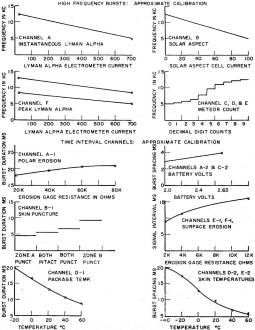
Fig. 5 - Some typical Lyman-alpha satellite calibration
curves are shown here.
The second type of solar Lyman-alpha radiation signal transmitted represents
an orbital peak or maximum value (channel F). Marked increases in solar Lyman-alpha
radiation are expected to take place during periods of solar flares. Solar flares
take place infrequently and at random and are of relatively short duration. While
possible, it is quite unlikely that a solar flare will take place as the satellite
is passing over a primary recording station. While leaving much to be desired, correlation
between visually observed solar flares and orbital peak values of Lyman-alpha signals
will permit collection of valuable data. Two magnetic memory units will be used
in storing and transmitting peak orbital values of these signals. One memory unit
will be storing information on the current orbit while the second memory unit is
transmitting the peak value stored during the immediately preceding orbit. Once
each orbit, on transition from darkness to daylight, a light-sensitive device is
used to interchange the function of the two memory units. The unit which has been
transmitting has its previous memory cancelled and begins to store data during the
next orbit. Simultaneously the unit which has been storing information starts to
transmit its stored data. Since the technique used permits the transmitted signal
to change only once each complete orbit, adequate utilization of this data is expected
from official recording stations. Two calibration curves are shown for peak Lyman-alpha
data in Fig. 5. Different frequency ranges are used for readout of the two
memory units. This permits individual calibration as well as a check on proper functioning.
Opportunity does exist for amateur observers to make a major contribution to
the solar Lyman-alpha radiation experiment. Valuable indeed would be a properly
prepared amateur recording showing instantaneous values of Lyman-alpha radiation
during the progress of a solar flare. Recordings of interest would be any showing
an electrometer current in excess of 200 microamperes. By use of the calibration
curve for channel A of Fig. 5, this can be translated into a telemetry signal
frequency. Thus, it can be seen that recordings of value would be those in which
the frequency in any Lyman-alpha burst momentarily drops below 10 kc.
Precise measurement of these signals requires elaborate equipment. Amateur observers
can make reasonably accurate determinations from simple listening tests. A little
practice will permit rather easy identification of the Lyman-alpha signal burst
channel. This information is distinguished as the first and longest of the often
repeated rhythmical alternation between channels A and B. It should be pointed out
that recordings played back at reduced speed will have the desired signal frequencies
correspondingly reduced. Thus a tape played back at one half of the recording speed
would be of interest if the Lyman-alpha burst frequency dropped below 5 kc. It is
suggested that a comparison test tape be prepared for ease in identifying valuable
signals. An audio oscillator would be used to record a 10 kc. signal at the same
tape speed planned for recording satellite signals. This tape would then be played
back at the same speed used for listening tests. This procedure provides automatic
compensation for changes in tape speeds.
Solar Aspect: A silicon solar cell located on the satellite equator will provide
information on the orientation of the satellite with respect to the sun. This data
is required by the Lyman-alpha experimenters for detector sensitivity calibration.
It will also provide accurate information on satellite spin and spin damping. This
signal is presented six times each telemetry frame on channel B. Calibration is
shown in Fig. 5.
Surface Erosion Experiments:
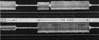
Fig. 6 - This is a portion of the telemetry record obtained
from a rocket flight. The record shows the collision of the rocket with a micrometeorite.
Erosion of the surface of the satellite will be studied by means of small erosion
gages attached to the outer shell. These gages consist of small glass plates on
which a thin-film metallic resistor has been deposited. The telemetry system will
detect the wearing away of this metallic film by monitoring changes in resistance
during this process. Reference to Fig. 5 shows two types of gages are used
for different sensitivity ranges. Thus a polar erosion gage providing information
on channel A1, consists of a very thin film having an initial resistance of 20,000
ohms. Thicker films on gages represented by channels E1 and F1 provide an initial
resistance of 2000 ohms. Resistance of all gages will increase as erosion takes
place. At anticipated erosion rates, ample information is expected from primary
receiving stations. Thus the resistance values are expected to undergo only minute
changes during intervals between official observations. Properly spaced amateur
recordings could provide vital information in the event of early complete breaks
in the metallic film. Amateur recordings could, under these circumstances, provide
the only source of information to distinguish between an abnormally high but uniform
erosion or collision with a single particle (s) of sufficient size to result in
destruction of gages on first impact.
Cadmium Sulphide Meteor Detector:
Another type of detector for meteoritic collision experiments uses a cadmium-sulphide
cell covered by an opaque layer. The cadmium sulphide is photoresistive in that
its electrical resistance decreases when exposed to light. This cell is initially
protected from sunlight by the opaque cover. As
meteorites puncture the protective layer, sunlight will be permitted to reach
the sensitive element. When the satellite is in sunlight, the resistance change
will reflect the amount of the opaque layer removed. The photoresistive element
is of a selected type having a long time constant. Thus the resistance changes will
take place only slowly so as to minimize effect of satellite spin. This information
is displayed on telemetry channel F2. No calibration for this channel is given in
Fig. 5. This channel will initially be at its high resistance value presenting
a burst spacing of about 11 milliseconds. As the opaque layer is punctured this
interval will become progressively shorter during the sunlit portion of each orbit.
Amateur recordings could provide much valuable information for this experiment.
Adequate coverage could provide accurate timing of collisions detected. Such recordings
could also permit the distinction between single collisions with large particles
and multiple collisions with small particles removing the same area of cell cover
material.
Skin-Puncture Experiment:
This experiment is designed to detect collision with particles of sufficient
collision energy to puncture the outer shell. Two pressure-tight zones are incorporated
into the satellite outer shell. Prior to launching, these two zones are initially
pressurized to significantly different pressures. A single differential pressure
measurement made between the two zones can indicate the puncture of either or both
zones. With both zones intact, the differential pressure gage would indicate the
initial value. When either zone becomes punctured its internal pressure will equalize
with the near perfect vacuum of the satellite environment. Thus with either one
of the two zones punctured, the differential pressure measurement will display the
pressure of the zone remaining intact. When both zones become punctured, the differential
pressure will be zero since both zones will be evacuated to ambient atmospheric
conditions. Amateur recordings could assist in more precisely determining the time
at which punctures occurred. If both zones were punctured in an interval between
primary recordings, amateur observations would be the only potential source of information
to permit determining whether separate punctures occurred or if a single particle
punctured both zones. This data is presented on telemetry channel B1.
Meteoritic Collision Experiment:
Sensitive microphones attached to the outer shell of the satellite are used to
detect collision with small particles in space. Magnetic memory units in the satellite
are used to store and continuously transmit information on the cumulative number
of such counts detected. Three channels of the telemetry system serve to provide
counting data in the form of three decimal digits. Consider, for example, the telemetry
channel C which provides units-count data. As can be seen from Fig. 5, the
frequency in this burst increases from about 5 kc. to 12.5 kc. in discrete intervals.
One such frequency change is made for each input count up to nine. Upon arrival
of the tenth count, channel C returns to 5 kc. ("zero" units count) while the frequency
in channel D makes the appropriate increase to indicate the tens count; i.e., the
number of times the unit count has returned to zero. Similarly, channel E frequency
will present hundreds digit information by advancing one "count" for each reset
of the tens digit counter. This can be seen to be similar to the operation of the
mileage indicator of an automobile speedometer. The units counter advances one digit
for each mile traveled. For each ten miles the units digit returns from nine to
zero while one count is added to the tens digit. The nature of these signals can
be further illustrated by reference to Fig. 6. The two oscillograms show similar
portions of two successive telemetry frames. Both display the final portion of the
units count and the complete tens count burst. The signals shown were extracted
from records made during a rocket flight in which satellite instrumentation equipment
was being test flown. The brief interruption of the tens burst is the equipment
"dead time" which occurs whenever a count is being received. This interruption is
many times shorter than the shortest burst spacing and would not be confused by
a practiced observer. The upper trace thus shows a time interval including an actual
collision of the rocket in flight with a meteoritic particle. The unit count burst
in this upper trace is at its highest (12.5 kc.) frequency representing a count
of "nine," while the tens count starts at a slightly lower (12 kc.) frequency representing
a count of "eight," thus indicating a cumulative count of 89. The hundreds count
is not shown but is unimportant in this illustrative discussion. Following this
collision the frequency of the tens count burst has increased to 12.5 kc. representing
a count of "nine" in the tens digit. The bottom oscillographic trace shows indeed
that the units count has returned to its low (5 kc.) frequency to indicate a "zero"
units count while the tens count remains unchanged at its "nine" count for a cumulative
count of 90.
No really satisfactory estimates are available as to the number of such collisions
to expect from a satellite in orbit around the earth. Counts of a few hundred or
less per orbit can be studied by means of the difference in cumulative count between
recording periods. The information transmitted presents total counts only up to
999 before returning to 000 to begin a new sequence. Therefore, high counting rates
extending into thousands of counts per orbit cannot be studied in this way. Such
large counting rates would be studied by change in total count over shorter time
intervals, such as the signal reception interval for a single receiving station
or occasional satellite transits which provide less than full orbit intervals between
recordings.
Many potential contributions could be made by amateur observers in the study
of collision between the satellite and micrometeorites. For example, in a single
orbit, a series of amateur records from properly distributed geographical locations
could establish whether particles are distributed at random or clustered in clouds.
Amateur recordings would also be of great value in the event of unanticipated high
counting rates. Ample data could also provide clues as to the possible origin of
such particles. Study of micrometeorites by means of satellites is a new field with
most meager background information upon which to base estimates and plan experimental
techniques. The subject is expected to be much better understood after the present
satellite experiment has been completed. Extensive useable records from a single
successful satellite would provide a sound basis for an exhaustive scientific study
and analysis.
Skin-Temperature Experiments:
Measurements of the temperature of the outer shell of the satellite are made
at two points. One temperature sensing element is located near one satellite pole;
i.e., near the spin axis. The second sensing element is located near the equator
of the satellite; i.e., the plane perpendicular to the spin axis passing through
the center of the sphere. Data on these two measurements are transmitted as burst
spacings on channels D2 and E2 respectively.
Virtually all heat transfer to and from the satellite in orbit will take place
by the process of radiation. Ambient atmosphere at satellite altitudes is so rarefied
as to make negligible any aerodynamic heating or heat transfer to or from this atmosphere.
The satellite will be heated by radiant energy received primarily from the sun and
the earth. Some heating will also be derived from power dissipation of internal
instrumentation equipment. The satellite will be cooled by radiating energy into
space. Satellite temperatures can be controlled to a certain extent by means of
coatings applied to the outer surface. These coatings permit selective control of
the ability of the satellite to radiate heat into space and its ability to absorb
radiant energy. Thus a satellite which was an efficient radiator and a poor absorber
would tend to run cold and vice versa. Precise temperature control is not possible
since coatings are applied prior to launching on the basis of assumed values of
many factors which affect the satellite temperature. For example, heating of the
satellite due to radiation from the sun will depend upon the length of time the
satellite remains in sunlight in each orbit. Variations in orbit cap. cause a variation
of nearly two to one in the absolute time per orbit which the satellite remains
in sunlight. As one further example, the energy radiated by the earth will undergo
radical changes with the amount of cloud cover. In spite of the many unpredictable
factors, it is expected that mean orbital temperatures of the outer shell will lie
between 0° C and 60° C (32° F and 140° F) under most unfavorable
conditions. Outer shell temperatures during any orbit will vary from ±5°
C to ±15° C from the orbital mean value as the satellite heats up when
in sunlight and cools when in. the earth's shadow.
Ample information on temperatures are expected from primary recording stations
for any satellites of a normal active life. Recordings made by amateur observers
would be of great value in the event of unexpected temperature extremes which could
result in early equipment or battery failures.
Instrumentation-Compartment Temperature:
Airborne electronic equipment is located in an internal instrumentation compartment.
This inner compartment will be thermally isolated from the outer shell so that heat
exchange will be a very slow interchange by radiation. This tends to isolate the
internal equipment from orbital temperature variations. The instrument compartment
temperature will thus remain relatively stable at a value a very few degrees above
the mean orbital temperature of the outer shell.
It can be seen that many potential contributions are possible from recordings
of satellite scientific signals prepared by amateur observers. The necessary equipment
is available to many now and could be prepared by others by inexpensive modification
of present equipment. Preferable tapes would be made on "stereophonic" tape recorders
with the satellite signal on one track and a reliable time base on the second track.
Suitable time base would be obtained from a stable oscillator or recording of signals
from WWV including a time announcement.
To be useable, any tapes must be accompanied by certain basic information as
follows:
(1) Name and address of the observer if tapes and their interpretation are to
be returned.
(2) Make and type of recorder on which tapes were prepared.
(3) Tape speed in inches per second at which recording was made.
(4) Number of channels and signals recorded on each.
(5) Date on which recording was made.
(6) Exact time at which recording was made including a.m. or p.m., time zone
(or Greenwich time), and whether daylight or standard time.
(7) Exact location at which recording was made, preferably including latitude
and longitude.
(8) Any special scientific data the record may be believed to contain.
All correspondence. relative to programs for receiving satellite signals or available
tapes should be addressed to U. S. Naval Research Laboratory, Washington 25, D.
C., Attention: Code 4105. Recorded tapes should not be mailed without further instructions.
Any tapes prepared early in the life of a satellite should be carefully preserved
until the fate of the satellite and its scientific experiments have been determined.
Such recordings could be of great value.
Posted November 20, 2019
|