|
After reading so many articles
about vintage vacuum tube radios and TVs in the older electronics magazines, it
makes me appreciate the relatively trouble-free products we enjoy today thanks to
semiconductor technology. Monthly columns were filled with troubleshooting advice
and tips for making modifications to factory designs that will enhance performance
and/or reduce the likelihood of premature failure. Although many tubes did outlast
the lifetime of the chassis in which they were installed, it was pretty much a given
expectation that sooner or later some tubes would need to be replaced - that is
why they were the only components that came installed in sockets for easy removal
and installation. Fortunately, because of the huge volumes produced, prices were
relatively low, and many stores - not just electronics shops - had self-serve
vacuum tube testing machines. Of course they also had a stock of replacement
tubes to sell you if any tested bad. If you want to get a feel for the situation
of the era, read through a few of John Frye's
Mac's Radio Service Shop techno-dramas, which are both informative and entertaining.
Why Tubes Fail Prematurely
 by Sol Heller by Sol Heller
Don't be too quick to blame the tubes themselves. Here are some of the many other
things to check.
Tubes, like humans, may live normal lives and die of old age - or they may be
carried off prematurely, possibly in the first flush of youth. When they die prematurely,
several groups of mourners want to know why.
The service technician wants to know, because he doesn't want a replacement to
bite the dust before its time. It means money out of his pocket.
The tube manufacturer wants to know, because he doesn't want his reputation -
or his bankroll - to suffer. If his tubes are not rugged enough, both will take
a beating.
The set designer - and set manufacturer - want to know because they don't want
their company to be accused of making poorly designed sets in which components break
down quickly.
The first matter that should logically occupy our attention is, why in general
do tubes blow prematurely? We will then be in a better position to figure out, when
a tube in a particular circuit goes bad, whether a defect in the tube's construction,
or some other cause, was responsible.
Tubes have ratings, established by the tube manufacturer, which must not be exceeded
during receiver operation. Among the most important of these ratings (with respect
to avoiding tube damage) are: maximum plate voltage; maximum plate dissipation;
grid No. 2 (screen) voltage; grid No. 2 input (screen dissipation); and peak heater-cathode
voltage. In the case of some tubes, these additional ratings are important: maximum
positive bias (extent to which the control grid may go positive, with respect to
the cathode); grid No.1 input (control grid dissipation); and the total cathode
current.
In the case of rectifiers, important ratings include: peak inverse plate voltage;
peak plate current (per plate); d.c. output current (per plate); and the peak heater-cathode
voltage. In the case of all tubes, the heater voltage must be maintained within
certain limits of the value specified by the tube manufacturer.
If one or more of a tube's ratings are exceeded for appreciable periods of time,
damage to the tube becomes likely. If the line voltage variations exceed ±10%,
for example, tube damage becomes possible.
In some cases, if tubes are not mounted properly, with respect to the vertical
or horizontal plane, or ventilation of the receiver is improper, tube damage can
result.
Insufficient Bias
Insufficient bias, in the case of a power-amplifier tube, may cause excessive
plate dissipation and result in damage to the tube. Every technician has seen the
plate of a 6BG6G glow red hot, when failure of the horizontal oscillator or a leaky
coupling capacitor has eliminated or reduced the bias of the horizontal-output tube
and increased its plate current. The heat generated, in some cases, is so great
that the solder in the plate cap melts, causing the plate clip and plate cap of
the tube to become soldered together.
When a horizontal-amplifier tube has been replaced, you should take out an "insurance
policy" on its successor's life by checking for the amount of drive to the tube.
This can be simply and quickly done by manipulating the drive control. Advance the
control until overdrive lines (vertical white lines) are seen in the picture. Then
turn the control back to a setting where the lines just disappear. When overdrive
lines cannot be obtained, insufficient drive to the tube may be present. If the
life of the original tube was short, a scope test of the drive-signal amplitude,
as well as the bias of the horizontal-output tube, is warranted.
An erratically oscillating horizontal-oscillator tube may be the reason that
a horizontal output tube has had a short (but not merry) life. This kind of trouble
can be added to the list of suspects if the customer reports that the screen used
to go dark at intervals, before a continuous darkness descended over the commercials.
When the horizontal oscillator is a 6SN7GT, such trouble is particularly likely.
When a horizontal-output tube has had a short life and the set is a series-filament
type, the explanation may lie in an open in one of the series filament lines (assuming
there are two in parallel). If the horizontal-output tube filament is in one filament
string, and the horizontal oscillator in another, trouble in the second string may
remove drive from the output tube by making the oscillator inoperative.
Another tube that tends to be highly allergic to loss of bias is the front-end
(r.f.) oscillator. When this local oscillator has a substantial plate voltage, and
negative grid bias is lost because of some circuit fault, the tube itself is very
likely to be damaged if it is operated without bias for an appreciable length of
time. A characteristic milky color (produced by the release of gas) is often seen
in the upper part of the tube under such conditions. A bias check of the r.f. oscillator
stage is therefore not unwarranted when premature demise of the tube is encountered.
A leaky coupling capacitor in a video i.f. stage not infrequently produces short
life in a video i.f. tube.
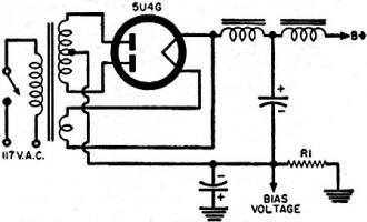
Fig. 1 - A drop in bias voltage may cause several tubes in a
set to be overdriven, overtaxing the rectifier.
A low-voltage rectifier may take the long count because of reduced bias in a
high-current tube, or in several tubes, of the particular set. A short-circuit to
ground of a bias resistor in the negative return of a rectifier (R1 in
Fig. 1) for instance, can cause the rectifier to overheat and become damaged. A
short between the electrodes of some tube other than the rectifier can also cause
rectifier current overload and resultant damage.
Plate and Screen Current
A circuit defect that eliminates plate-current flow in a high-current tube, but
permits screen current to flow in that tube, is likely to cause screen dissipation
to be exceeded, since electrons that normally travel beyond the screen, to the plate,
will now pass through the screen circuit. An open-circuit in a flyback transformer,
or in the output transformer of an audio power-amplifier stage, may cause such a
condition. An inoperative damper tube, in the case of some TV receivers, can result
in the removal of plate voltage from the horizontal-output tube, without causing
the screen current of the tube to be interrupted.
Sometimes a defective horizontal-output transformer - or a replacement transformer
that is not the correct type - can dispose of the horizontal-output tube before
its time. Excessive plate dissipation is what damages the tube under such conditions.
Premature death of a low-voltage rectifier is sometimes due to the fact that
the tube is being worked too close to its maximum current ratings. An increase in
line voltage, or some circuit trouble that causes the d.c. current passed by the
rectifier to increase, can readily push the tube over the top. One set manufacturer,
for example, ran into this trouble when he used a 5Z4 as rectifier in one of his
TV chassis. Replacement of the 5Z4 by a 5V4G, whose plate current ratings are considerably
higher, remedied the trouble.
Excessive plate current surges in a rectifier can cause short life. The surges
commonly occur when a set is first turned on. An input filter capacitance that is
too large in value is one possible source of the trouble. A technician sometimes
replaces the original capacitor with one of a larger value in order to boost the
d.c. voltage output of the rectifier. He may not realize that the "boost" is really
a "knock," in this case, with respect to rectifier life!
High Heater Voltage
Excessive filament voltage reduces the life of a tube's heater. It also damages
the cathode. In series-filament receivers, the voltage surges that take place when
the set is first turned on are a cause of reduced tube life, particularly in the
case of older-type tubes. Specially designed tubes of more recent vintage, such
as the 3AL5, 5AQ5, etc., are less vulnerable to voltage surges. In some TV receivers,
an open circuit in the filament of a tube in one string may expose the filaments
of tubes in another string to excessive voltages. An open circuit in a resistance
that is in parallel with a tube filament will also cause a larger-than-normal voltage
to be developed across the filament.
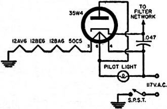
Fig. 2 - Failure to replace a blown pilot light tapped across
a rectifier filament may hasten death of tube.
When a blown pilot light in a radio using a 35W4-type rectifier (see Fig. 2)
is not replaced immediately, and the radio is operated without the replacement,
the rectifier's life will be greatly reduced. The reason is that the voltage developed
across the section of the filament with which the pilot light is in parallel is
increased; the voltage surge that appears across this section of the filament when
the set is first turned on is, not infrequently, large enough to blow it at once.
In some instances, short life of a tube in a series-filament string is due to
an excessively low cold resistance of one of the tube filaments in the string. Tube
filaments in series with the filament in question will be subjected to higher-than-normal
surge voltages, and short life of one or more of these tubes becomes possible. When
a premature open filament is encountered in the case of a series-filament set, and
no more likely cause of the trouble can be found, it is worth while to check the
cold resistances of the filaments in the string affected. The values of resistances
obtained should be compared with the filament resistance values of identical-type
new tubes. An ohmmeter capable of reading very low values of resistance accurately
will be needed in the case of some tubes.
Excessive filament voltage is also a possible cause of premature failure of a
high-voltage rectifier. The excess may be due to a higher-than-normal line voltage;
to decrease in the value of the filament-dropping resistor in series with the rectifier;
to arcing between plate and filament of the rectifier; or to improper positioning
of the filament winding on the core of the set's flyback transformer itself.
Tests for the presence of most of these troubles are familiar; the only condition
that warrants comment is arcing between plate and filament. Such arcing occurs when
the peak inverse plate voltage rating of the rectifier is exceeded. The only commonly
used rectifier that is likely to suffer from this trouble is a 1X2, due to its relatively
low inverse peak voltage rating - 15,000 volts - compared to a 30,000-volt peak
rating for a 1B3. Replacement of the burnt-out 1X2 with a 1X2A, which has an inverse
peak volt-age rating of 20,000 volts, will greatly reduce the likelihood of premature
failure. Low Heater Voltage
Many technicians are not aware that insufficient filament voltage may shorten
tube life. Here's the reason: Nearly all receiving tubes have oxide-coated cathodes
which operate at a temperature of approximately 777 degrees centigrade. When a cathode
of this type is operated at a temperature considerably below 777 degrees (due to
a decrease in filament voltage), and electrode voltages other than the filament's
are normal, the cathode coating is damaged. This occurs because the space charge
(cloud of electrons) in the vicinity of the cathode, which normally limits plate
and screen currents to safe values, is no longer large enough to perform such a
protective function. The peak currents the cathode may supply under the circumstances
are in excess of what it was designed to deliver. Arcing between cathode and other
electrodes, as well as coating damage due to excessive peak currents, becomes possible.
Insuring that filament voltage is normal is especially important in the case
of the high-voltage rectifier and the cathode-ray tube. In the case of the high-voltage
rectifier, normal filament voltage gives the best chance of long life to a tube
that is perhaps subject to greater stresses than any other tube in the receiver.
In the case of the picture tube, it is important to avoid below-normal filament
voltage - as well as any other deviation from normal electrode voltages - because
of the expense of a replacement.
Heater-Cathode Voltage
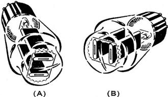
Fig. 3 - When a receiver is up-ended for service, note the horizontal
plane in which the elements of the rectifier fall. Certain types, when kept in the
wrong position, will suffer damage due to internal sagging of the filaments.
When the peak heater-cathode volt-age of a tube is exceeded, the insulation between
heater and cathode is likely to break down, either partially or completely. The
technician is well-advised to check the difference between heater and cathode potentials
when an expensive tube has developed a cathode-heater short, or considerable leakage
between the two electrodes. Many breakdowns between the cathodes and heaters of
cathode-ray tubes have been reported; an excessive potential difference between
these electrodes is often responsible. The trouble is likely to develop when the
peak cathode-heater voltage rating of a tube is a relatively low one.
Damper tubes are notorious for cathode-heater breakdowns, due to the very large
pulse voltages that often develop, or tend to develop, between cathode and ground.
Breakdown between cathode and heater of the damper may damage the heaters of other
tubes that are connected in parallel or in series with the damper filament. When
premature failures of damper tube filaments, or filaments of other tubes tied in
with the damper heater, are encountered, a check should be made, to determine whether
a damper cathode-bypass capacitor has open-circuited, or a connection between a
positive line and the damper filament has been interrupted. (The positive line connection
reduces the difference in d.c. potential between damper filament and cathode.)
Improper Lead Dress
Cases have occurred where a tube has been destroyed because of sustained arcing
between a high-voltage lead and the envelope of the tube. A number of instances
involving the plate lead of a 1B3 high-voltage rectifier and the envelope of a 6W4
damper were reported by one set manufacturer. A tell-tale marking on the tube envelope
will generally indicate that such arcing has taken place, and requires remedying
before the tube is replaced.
Insufficient Ventilation
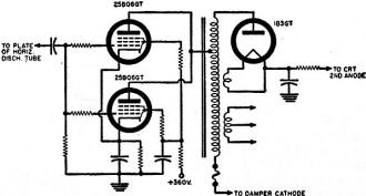
Fig. 4 - Where two horizontal-output tubes are used and one is
to be tested, be careful about operating the set while only one of the tubes is
hot. Damage may result to latter.
Proper ventilation is needed to keep the temperature of a tube envelope from
exceeding a safe value. Excessive heating of the envelope promotes gas formation
within the tube. Good ventilation is particularly important in the case of high-current
tubes, such as video amplifiers, deflection output tubes, audio power amplifiers,
and low-voltage rectifiers. Approximately half of the heat of the tube envelope
is dissipated by convection, or the flow of air currents past the tube; the other
half is dissipated by radiation. Convection requirements demand that cool air be
permitted to flow among the tubes. When a customer places the back of his set flush
up against a wall (assuming that the back of the set permits such flush positioning),
proper convection cooling is not likely, and excessive heating of the tubes may
shorten the lives of one or more of them.
Proper heat dissipation via radiation requires that surfaces cooler than the
tube envelope be near the tube, so that the tube can radiate its heat away to the
cooler surfaces. If the set designer has not provided conditions suitable for proper
radiation of heat - if he has, say, mounted a large, high-wattage resistor near
a rectifier tube, causing surrounding surfaces to become hot - long life for the
tube is not likely.
Sometimes a set manufacturer places a shield around a high-current tube, forgetful
of the serious rise in envelope temperature that such a procedure produces. Numerous
subsequent reports of tube breakage cause a production change to be hurriedly issued,
requesting removal of the shield. The moral to the technician is, never put a shield
around a high-current tube, to remedy some trouble or other; the disease may be
cured, but the patient will die.
(Editor's Note: If you feel a tube shield is really necessary, try puncturing
several holes along its surface. While this will scarcely impair shielding action,
it will also permit better cooling. Thus, a second moral: sometimes you can eat
your cake and have it.)
Tubes mounted on vertical chassis are particularly subject to overheating, and
require especially good ventilation for assurance of long life.
Servicing Hazards
When the service technician's experience is not extensive, tube damage from time
to time is inevitable. Space is not available here to discuss all the possible ways
by which the inexperienced technician may produce premature tube failure; some of
the less common ones, however, will be considered.
When a set using a pair of parallel-connected horizontal-output tubes (see Fig.
4) is being serviced, and the set is turned off briefly to permit one of the tubes
to be replaced, the second one may be damaged if the set is immediately turned on
again. The second tube is still hot, while the replacement for the first one is
cold; an unequal distribution of currents consequently takes place between the tubes.
The hot tube may draw excessive plate current long enough to be damaged before the
new tube heats up. To prevent such damage, the second tube should be allowed to
get cold, before the set is turned on.
When a TV set is turned on its side for servicing and left in this position for
a considerable period of time, damage to certain makes of 5U4 tubes may occur. In
the types referred to, filament and plate are in a horizontal plane when the tube's
long axis is parallel to the workbench (see Fig. 3). A slight amount of expansion
and sag in the filament may cause a short between filament and plate. In other 5U4's
the relation of keyway to electrode structure is such that the filament and plate
are in a vertical plane (Fig. 3B) where the tube's long axis is parallel to the
workbench, making a filament-to-plate short due to sag much less likely. Because
of this phenomenon it is well to check any 5U4 replacement that will be mounted
in any but the upright position.
Sometimes technicians who are connecting the audio amplifier of a TV set or radio
to a record player will cause the plate and screen circuits of r.f. and/or i.f.
tubes to be interrupted during phono operation. The procedure is not a wise one,
since it tends to shorten the lives of the tubes involved, say tube designers.
Posted August 3, 2020
|


