|
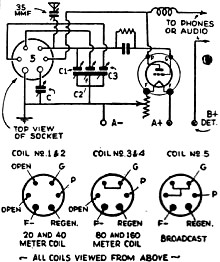
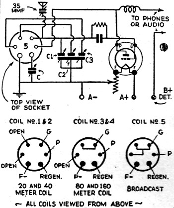
Band Spread Trick
I am submitting a short-wave kink which I have found truly practical and
very efficient. It is a band-spread kink which is truly automatic and which
changes condensers when the different plug-in coils ale inserted. This system
is really very flexible and may be varied to suit the fancy of the builder.
Connections of the secondaries and ticklers are shown for five different bands:
C is regeneration condenser, .00025 mf.; C1, a condenser to spread 20- and
40-meter bands; C2 will spread the 80- and ten-meter band; C3 covers the broadcast
band. - Wm. Porter.
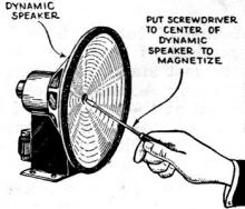
Magnetizing Stunt
Many experimenters have had occasion to need a tool which has been magnetized
in order to retrieve screws, nuts, or washers which have been dropped in the
process of assembling radio apparatus. The drawing shows how a screwdriver
or similar implement may be magnetized by bringing it in contact with the
"pole-piece" of a dynamic speaker. Of course the speaker must be running in
order that it will be magnetized. This stunt will only work of course on iron
or steel tools and it will attract only like metal. Brass, copper, or aluminum
will not be attracted to the magnetized screwdriver, of course. - Luther Burkhardt.

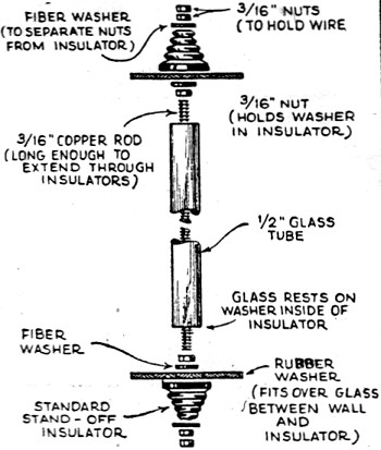
Handy Lead-In Insulator
If a suitable lead-in insulator is not on hand, one can be constructed
from a pair of regular stand-off insulators by the following method: Remove
the fittings from two of these insulators and procure a length of 3/16-inch
threaded brass or copper rod, 4 1/2-inch fiber washers, 6 nuts to fix the
rod and a length of 1/2-inch glass tubing; also make two rubber washers 3
inches in diameter with a. 3/4-inch center hole. These can be cut from an
old inner tube. I am using a pair of these insulators for bringing in a transposed
lead-in and I find them very satisfactory. - John Schlener, Jr.

Homemade Coil Form
When making plug-in coils, especially the ones with larger windings,
I found that the usual tube base was too short, In the drawing it can be seen
that two tube bases are used; by removing the pins of one and cementing it
in the top of the other, we have a very neat coil form.
It is necessary, however, to wind the required number of turns on the lower
coil form before the two forms are cemented together. Then wind the other
form and run the two ends of the wire down through the holes which were left
when the prongs were cut off. The drawing clearly shows how the entire unit
is assembled. - Milton Sarchett.
|
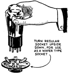
Inverted Socket
There are many times when I have found that a socket could not be mounted
in the way it was designed for, and have found that it was possible to turn
it up-side-down and overcome the difficulty. A sub-panel socket or wafer socket
can be turned up-side-down and mounted on top of the panel as shown in the
drawing. Of course, all sockets, due to their peculiar contact construction
will not work this way. However, I have found that 90% of them will. I have
also found that the base-mounting socket could be mounted underneath the sub-panel
by replacing the screws which hold the contact and face them downward. - S.
Javna.
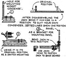
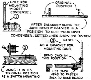
Uses for Old Phone Jacks
Undoubtedly nearly every experimenter who reads this magazine can find
a large number of discarded old-fashioned phone jacks in the junk box. These
should be saved by all means because they can be put to various uses such
as shown in the accompanying drawing. In the drawing we have the base of the
jack forming an "L" bracket which can be used for mounting midget condensers,
volume controls, switches, and a number of other instruments. - James Slocum.
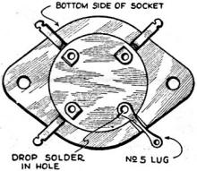
Mending Tube Sockets
How many times have you broken the terminal on your last tube socket? This
happened: to me one time and as I could not obtain another socket immediately,
I had to devise a method of repairing the: damaged one. After much thought,
a No. 5 soldering lug was finally brought to play. This was attached to the
under side of the socket with a drop of solder and presto, the socket was
as good as new! However, you will find that most of the metal parts on sockets
are nickel-plated and it will be necessary for you to scrape the nickel-plated
rivet until all nickel plating is removed and the brass or other metal shows
through, otherwise the solder will not adhere to it. When you are in a "jam"
for a socket some time, try repairing your old ones in this manner and see
how nicely it works out. - Edward Kolakowski,
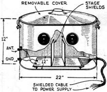
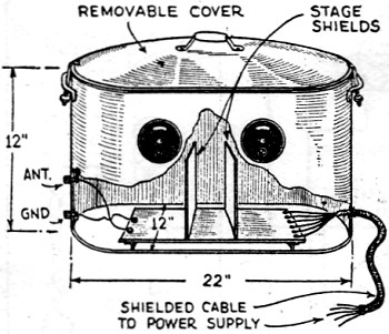
Wash-Boiler Radio Cabinet
After completing a 4-tube short-wave receiving set I found, much to' my
disappointment that it was an excellent receiver of passing automobiles-ignition
noise, of course! The next move was to completely shield the receiver but
funds were low so the idea, presented in the drawing, came into being. The
cabinet I used was made from an old wash boiler which, incidentally, is copper
and provides very effective shielding. The removable cover offers ease in
getting at the inside of the receiver for changing coils or tubes. A shielded
power cable was also used in order to eliminate pick-up. This in connection
with the thorough shielding and the use of a good antenna, practically eliminated
the interference. - C. E. Judson.
|
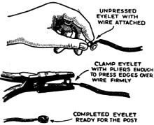
Handy Cable Lugs
Experimenters who have found difficulty in making a neat binding post connection,
when using stranded hook-up wire, will find this odd wrinkle a cheap method
or making positive contact. A number or eyelets (obtainable at any stationery
store) and a pair of pliers comprise the necessary equipment. First, twist
the strands of the end of the wire to be connected and loop this terminal
about one of the eyelets; clamp the eyelet firmly to the pliers, and it will
be found that the end or the wire is being gripped between the two sides of
the eyelet. The latter can then be slipped on and off the binding post rapidly,
and without danger of the wire being forced from under the head of the post,
as often occurs when using stranded hook-up wire. - Walter Kells.
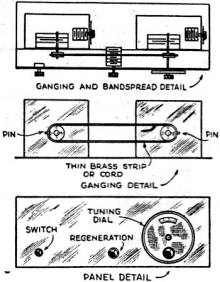
Improving Super Wasp
Brass Wheels are put on the two shafts of band-spreading condensers. This
is simple enough but the detector band-spreading condenser's shaft will have
to be removed and a 4-inch shaft inserted so that shaft may reach the new
dial on the new panel. The brass wheels are now tied together by means of
a piece of good fishing twine as shown in the sketch. If one prefers, the
twine may be replaced by a metal strip similar to the one used in the Atwater
Kent receiver. If twine is used a knot is made about the pin in each of the
brass wheels. - Francis E. McGee. W3DM.

Uses for Fahnestock Clips
By cutting off and bending Fahnestock clips, as shown in the drawing, a
very handy plug-in coil receptacle can be constructed. The drawing shows the
method used in mounting these clips. The contacts for the coil are ordinary
machine screws which are allowed to protrude and fit in the slot of the clip.
The clip is to be formed so that when the coil is pushed down into them they
will bear similarly against the nut which holds the screw to the coil form.
Two windings are shown on the coil; however, this could be increased to three
or four windings with a consequent increase in the number of clips. - Wm.
H. Eaton.
|