|
February 1935 Short Wave Craft
 [Table
of Contents] [Table
of Contents]
Wax nostalgic about and learn from the history of early electronics. See articles
from Short Wave Craft,
published 1930 - 1936. All copyrights hereby acknowledged.
|
Anyone other than a complete
novice (Ham pun intended) at radio and antenna work is familiar with the basics
types of directional antennas presented here. However, the universe of people knowledgeable
about such things was very small in 1935, when this article appeared in Short
Wave Craft magazine. An effort to educate operators and designers was really
just beginning. The ½-wave dipoles shown here for the transmitter are somewhat
directional at 2 dBi, and full-wave square loop antennas for receiving have
a gain of around 3 dBi. However, the most significant direction-finding feature
of a loop antenna is the comparatively deep null in its radiation pattern in the
plane of the wire. That explains why direction-finding equipment, such as those
on aircraft, typically use a loop antenna. When maximum precision is needed, Yagi,
log periodic, parabolic dish, or other high gain antennas will be used.
Direction Finding with "Ultra Shorts"
Diagrams showing how to use "loop" aerials for ultra short-wave
work.
Recently in this page, we mentioned some experiments which appeared in Wireless
World, regarding the reception of ultra-short waves with loop aerials. In this resume,
we pointed out that much work remained to be done along the lines of development
of aerials and radiating systems for ultra-short wave transmission and reception.
In a more recent issue of the above publication, some further details have been
presented, including an explanation for the apparent discrepancy in the direction
of transmission of the very high frequency waves.
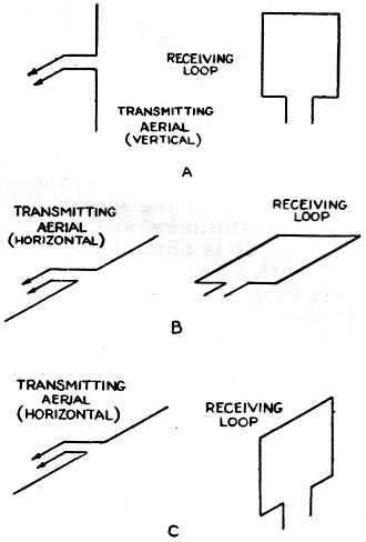
It will be remembered that with a horizontally polarized transmitter, it was
possible to receive signals with a vertically polarized loop, but with its plane
at right-angles to the direction of the transmitter.
In the later article, it is shown how this is possible. If the loop is pointing
toward the transmitter, as at A in the accompanying sketch, a signal will be picked
up in the loop. Now, if the loop is maintained in the same position, but the transmitter
polarized in a horizontal plane, the field is everywhere at right angles to the
winding of the loop, and therefore produces no EMF in it; this position gives minimum
signal strength. But if the loop is set as at C, the electrical field will be parallel
to its top and bottom, and will induce in these two sides EMF's which are opposed
to each other around the loop. Since all parts of the loop are now equidistant from
the transmitter, the two EMF's should have the same magnitude and phase, so that
the resultant EMF around the loop would be zero. But, if for any reason, the field
is non-uniform in the vertical plane so that the EMF, say, in the top of the loop
is greater than that in the bottom, there will be a resultant EMF around the circuit.
In practice, the presence of the receiver, just below the loop will probably
cause sufficient distortion of the field, while there is also the effect of the
earth to be considered, so that reception in this way becomes possible.
Posted July 10, 2024
(updated from original post
on 8/4/2017)
|